•
•
Parameter 4-38 Tracking Error Ramping Timeout
Table 284: Parameter 4-38 Tracking Error Ramping Timeout
4-38 Tracking Error Ramping Timeout
Parameter type: Range, 0 - 60 s
Change during operation: True
Enter the timeout period during which an error greater than the value set in parameter 4-37 Tracking Error Ramping while ramping is
allowed.
Parameter 4-39 Tracking Error After Ramping Timeout
Table 285: Parameter 4-39 Tracking Error After Ramping Timeout
4-39 Tracking Error After Ramping Timeout
Parameter type: Range, 0 - 60 s
Change during operation: True
Enter the timeout period after ramping where parameter 4-37 Tracking Error Ramping and parameter 4-38 Tracking Error Ramping
Timeout are still active.
5.5.4 4-4* Speed Monitor
Parameter 4-43 Motor Speed Monitor Function
Table 286: Parameter 4-43 Motor Speed Monitor Function
4-43 Motor Speed Monitor Function
Default value: Size related
Change during operation: True
N O T I C E
This parameter is only available in the flux control principle.
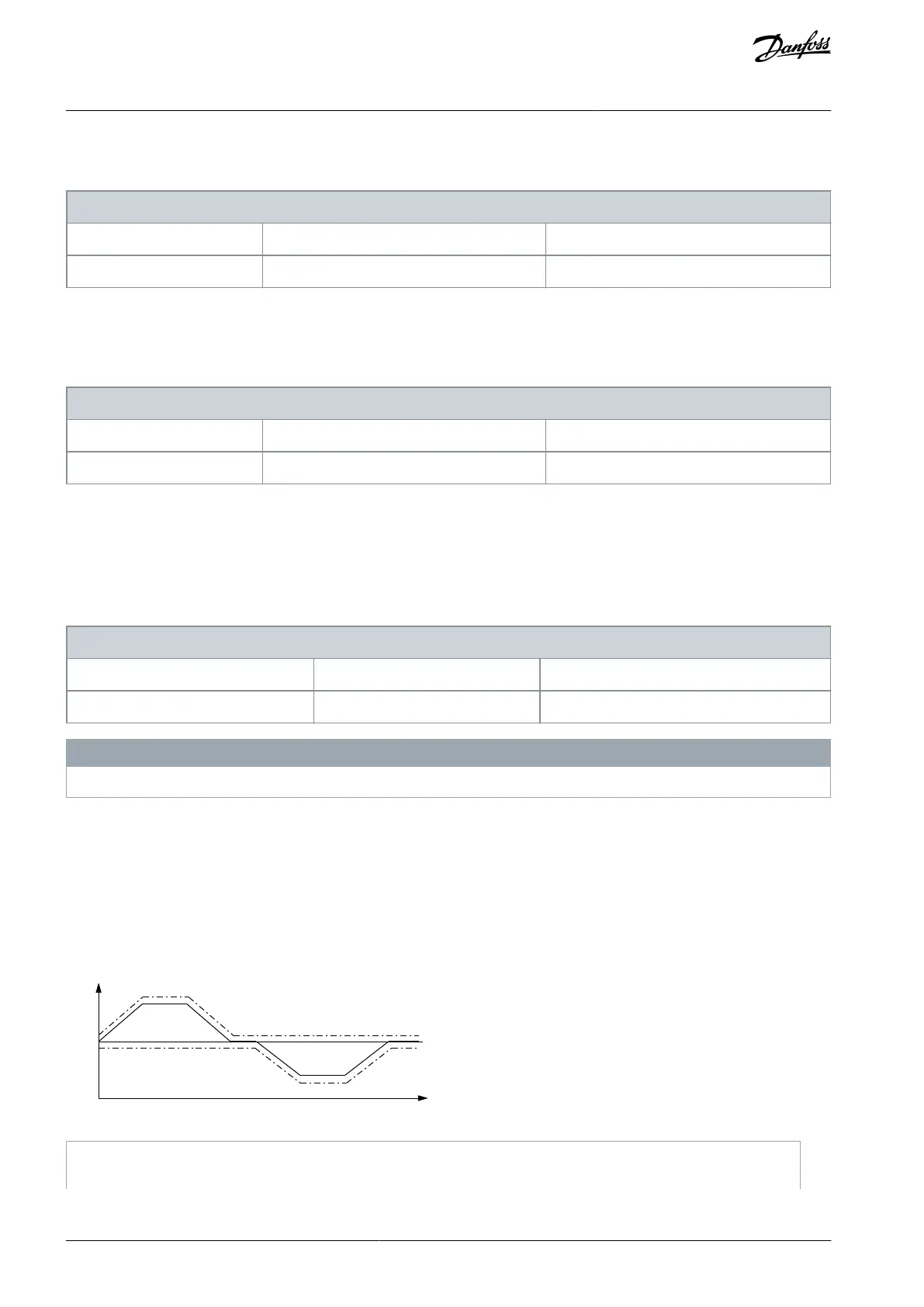
Select how the drive reacts when the motor speed monitor-function detects overspeed or wrong rotation direction. When the mo-
tor speed monitor is active, the drive detects an error if the following conditions are true for a time period specified in parameter
4-45 Motor Speed Monitor Timeout:
The actual speed differs from the reference speed in parameter 16-48 Speed Ref. After Ramp [RPM].
The difference between the speeds exceeds the value in parameter 4-44 Motor Speed Monitor Max.
In speed closed loop, the actual speed is the feedback from the encoder measured during the time defined in parameter 7-06 Speed
PID Lowpass Filter Time. In open loop, the actual speed is the estimated motor speed.
nRef
-nRef
0rpm
Time
e30be199.11
Illustration 58: Speed Reference and Maximum Allowed Speed Difference
Parameter 16-48 Speed Ref. After Ramp [RPM]
AU275636650261en-000101 / 130R0334162 | Danfoss A/S © 2022.12
Parameter Descriptions
VLT AutomationDrive FC 301/302
Programming Guide

 Loading...


