EasyManuals Logo

Danfoss VLT HVAC Drive FC 102 Programming Guide

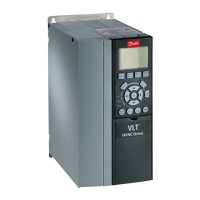
Danfoss VLT HVAC Drive FC 102
722 pages
To Next Page IconTo Next Page
To Previous Page IconTo Previous Page
Page #16 background imageLoading...
Page #16 background image
Input polarity of control terminals
12 13 18 19 27 29 32 33 20 37
+24 VDC
0 VDC
e30bt106.10
PNP (Source)
Digital input wiring
Illustration 2: PNP (Source)
NPN (Sink)
Digital input wiring
12 13 18 19 27 29 32 33 20 37
+24 VDC
0 VDC
e30bt107.11
Illustration 3: NPN (Sink)
N O T I C E
Control cables must be shielded/armored.
AU275636650261en-000101 / 130R033416 | Danfoss A/S © 2022.12
Electrical Diagrams
VLT AutomationDrive FC 301/302
Programming Guide

Table of Contents

Other manuals for Danfoss VLT HVAC Drive FC 102

Questions and Answers:

Question and Answer IconNeed help?

Do you have a question about the Danfoss VLT HVAC Drive FC 102 and is the answer not in the manual?

Danfoss VLT HVAC Drive FC 102 Specifications

General IconGeneral
EnclosureIP20, IP21, IP55
Ambient Temperature Range-10°C to +40°C
Storage Temperature Range-25°C to +70°C
Relative Humidity5-95% (non-condensing)
Communication ProtocolsModbus RTU, BACnet, Profibus
CertificationsCE, UL, cUL
Control PrinciplePWM
Cooling MethodForced air cooling
Input Voltage200-240V, 380-480V, 525-600V
Control Modessensorless vector control, closed loop vector control

Related product manuals