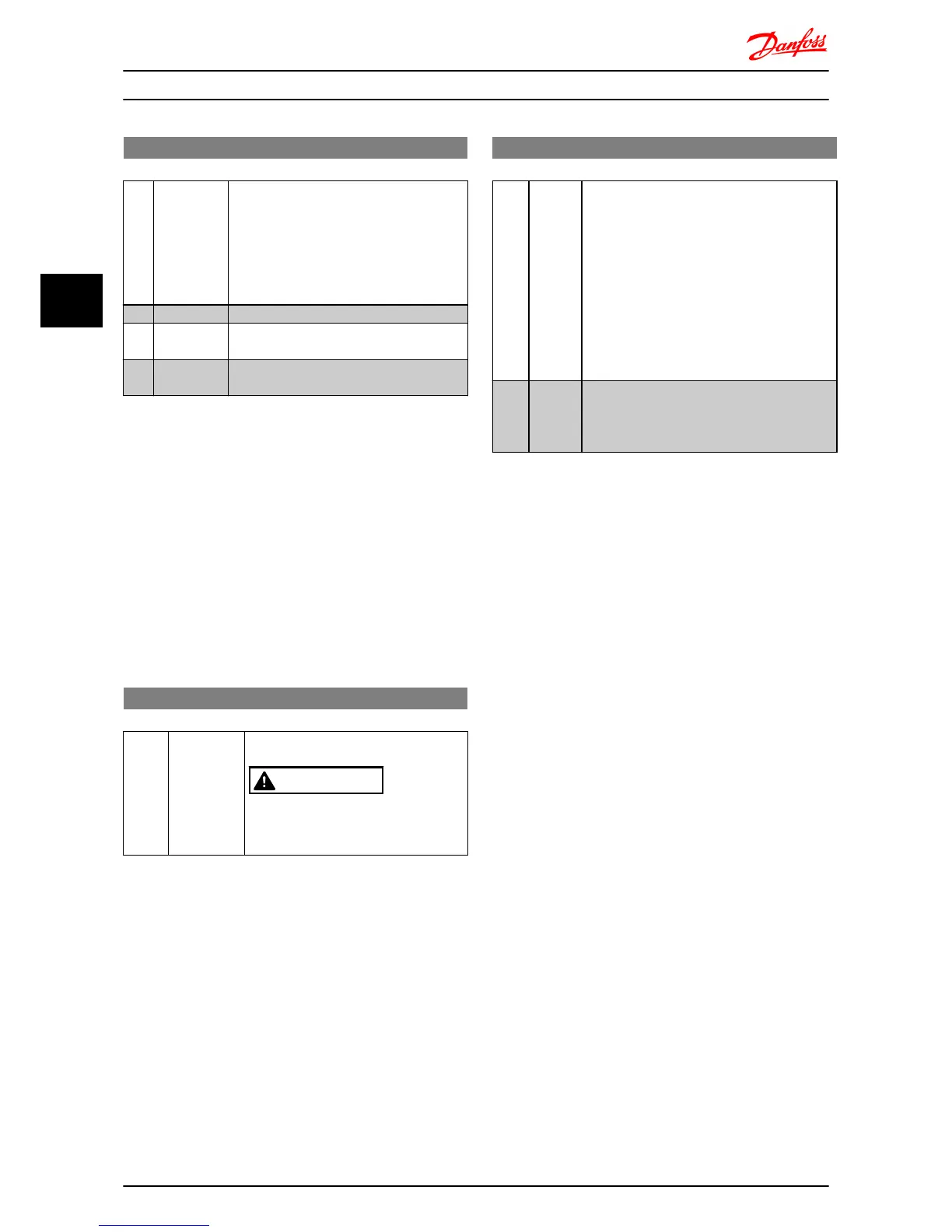
2-17 Over-Voltage Control
Option: Function:
Use Over-voltage Control (OVC) to reduce
the risk of the frequency converter tripping
due to an over voltage on the DC link
caused by generative power from the load.
An over-voltage occurs eg. if the ramp down
time is set too short compared to the actual
load inertia.
[0] * Disabled The OVC is not active/required.
[1] Enabled, not
at stop
OVC is running unless a stop signal is active.
[2] Enabled OVC is running, also when a stop signal is
active.
NOTE
If Resistor Brake has been chosen in 2-10 Brake Function
the OVC is not active even though enabled in this
parameter.
4.3.4 2-2* Mechanical Brake
For hoisting applications an electro-magnetic brake is
required. The brake is controlled by a relay, which releases
the brake when activated.
The brake activates if the frequency converter trips or a
coast command is given. Furthermore, it activates when
motor speed is ramped down below the speed set in 2-22
Active Brake Speed.
2-20 Release Brake Current
Range: Function:
0.00 A* [0.00-100 A] Select motor current at which mechanical
brake releases.
CAUTION
If start delay time has passed, and
motor current is below Release brake
current, frequency converter trips.
2-22 Activating Mechanical Brake
Range: Function:
If the motor is stopped using ramp, the
mechanical brake is activated when motor
speed is less than Active Brake Speed.
Motor is ramped down to stop in the following
situations:
•
A start command is removed (stand
by)
•
A stop command is activated
•
Quick-stop is activated (Q-stop ramp is
used)
0 Hz* [0-400
Hz]
Select motor speed at which mechanical brake
activates when ramping down.
Mechanical brake automatically activates if
frequency converter trips or reports an alarm.
Parameter Descriptions
VLT
®
Micro Drive FC 51 Programming Guide
20 MG02C602 - VLT
®
is a registered Danfoss trademark
44

 Loading...


