4.7 Parameter Group 6: Analog In/Out
4.7.1 6-** Analog In/Out
Parameter group for configuring analog inputs and
outputs.
4.7.2 6-0* Analog I/O Mode
Parameter group for setting up the analog I/O configu-
ration.
6-00 Live Zero Timeout Time
Range: Function:
The Live Zero function is used for monitoring
the signal on an analog input. If the signal
disappears, a Live Zero warning is reported.
10 s* [1-99 s]
Set delay time before Live Zero Timeout Function
is applied (6-01 Live Zero Timeout Time).
If the signal reappears during the set delay,
timer will be reset.
When live zero is detected, the frequency
converter freezes output frequency and starts
Live Zero Timeout timer.
6-01 Live Zero Timeout Function
Option: Function:
Function is activated if input signal is below
50% of value set in 6-10 Terminal 53 Low
Voltage, 6-12 Terminal 53 Low Current or 6-22
Terminal 60 Low Current.
[0] * Off Function is disabled.
[1] Freeze
output
Output frequency remains at value it had
when live zero was detected.
[2] Stop Frequency converter ramps down to 0 Hz.
Remove live zero error condition before
restarting frequency converter.
[3] Jogging Frequency converter ramps to jog speed, see
3-11 Jog Speed.
[4] Max Speed Frequency converter ramps to Motor Speed
High Limit, see 4-14 Motor Speed High Limit.
[5] Stop and
Trip
Frequency converter ramps down to 0 Hz
and then trips. Remove live zero condition
and activate reset before restarting the
frequency converter.
4.7.3 6-1* Analog Input 1
Parameters for configuring scaling and limits for analog
input 1 (terminal 53).
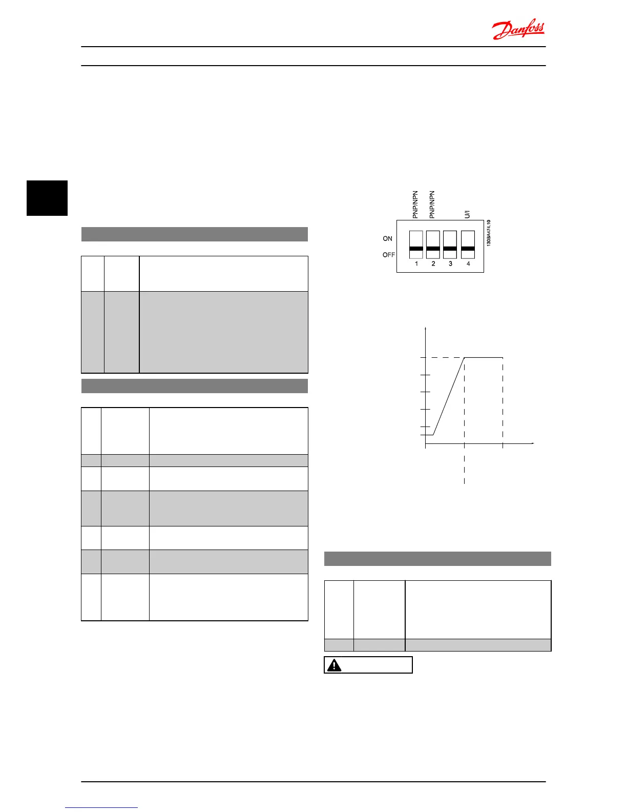
NOTE
Micro switch 4 in position U:
6-10 Terminal 53 Low Voltage and 6-11 Terminal 53 High
Voltage are active.
Micro switch 4 in position I:
6-12 Terminal 53 Low Current and 6-13 Terminal 53 High
Current are active.
Illustration 4.7
Illustration 4.8
6-10 Terminal 53 Low Voltage
Range: Function:
This scaling value should correspond to
minimum reference value set in 6-14
Terminal 53 Low Ref./Feedb. Value. See
also 4.4 Parameter Group 3: Reference/
Ramps.
0.07 V* [0.00-9.90 V] Enter low voltage value.
CAUTION
The value must be set to min. 1 V in order to activate the
Live Zero Timeout function in 6-01 Live Zero Timeout
Function.
Parameter Descriptions
VLT
®
Micro Drive FC 51 Programming Guide
32 MG02C602 - VLT
®
is a registered Danfoss trademark
44

 Loading...


