4.6 Parameter Group 5: Digital In/Out
4.6.1 5-** Digital In/Out
The following describes all digital input command
functions and signals.
4.6.2 5-1* Digital Inputs
Parameters for configuring the functions for the input
terminals.
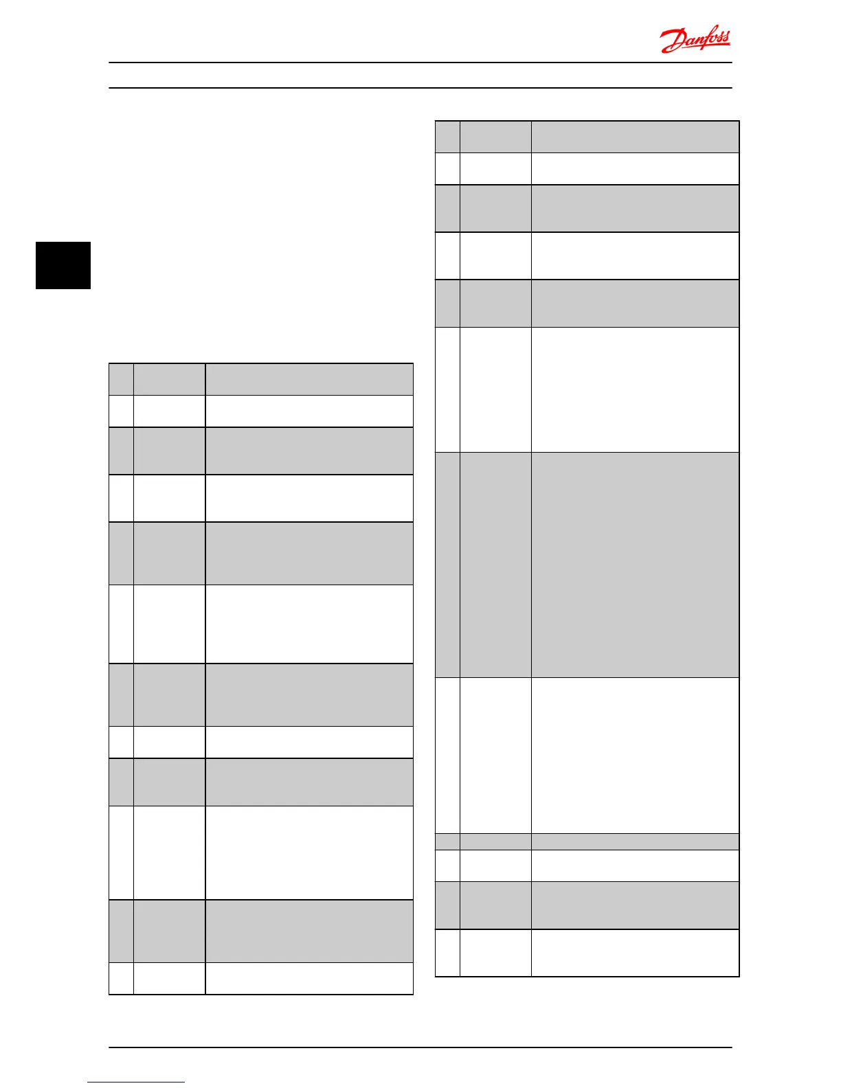
The digital inputs are used for selecting various functions
in the frequency converter. All digital inputs can be set to
the following:
[0] No Operation The frequency converter will not react to
signals transmitted to the terminal.
[1] Reset Reset the frequency converter after a Trip/
Alarm. Not all alarms can be reset.
[2 ] Coast Inverse Coasting stop, inverted input (NC). The
frequency converter leaves the motor in free
mode.
[3] Coast and
reset inv.
Reset and coasting stop inverted input (NC).
The frequency converter resets and leaves
the motor in free mode.
[4] Quick stop
inverse
Inverted input (NC). Generates a stop in
accordance with the quick-stop ramp time
set in 3-81 Quick Stop Ramp Time. When
motor stops, shaft is in free mode.
[5] DC-brake inv. Inverted input for DC braking (NC). Stops
motor by energizing it with DC current for a
certain time period, see 2-01 DC Brake
Current. Function is only active when value
in 2-02 DC-Braking Time is different from 0.
[6] Stop inv. Stop inverted function. Generates stop
function when selected terminal goes from
logical level “1” to “0”. Stop is performed
according to selected ramp time.
[8] Start Select start for a start/stop command.
1 = Start, 0 = stop.
[9] Latched start Motor starts if a pulse is applied for min. 2
ms. Motor stops when Stop inverse is
activated.
[10] Reversing Change direction of motor shaft rotation.
Reversing signal only changes direction of
rotation; it does not activate start function.
Select [2] Both directions in 4.10 Motor Speed
Direction.
0 = normal, 1 = reversing.
[11] Start
reversing
Use for start/stop and for reversing at the
same time. Signals on start [8] are not
allowed at the same time.
0 = stop, 1 = start reversing.
[12] Enable start
forward
Use if motor shaft must rotate clockwise at
start.
[13] Enable start
reverse
Use if motor shaft must rotate counter-
clockwise at start.
[14] Jog
Use for activating jog speed. See 3-11 Jog
Speed.
[16] Preset
reference bit
0
Preset reference bit 0, 1 and 2 enables a
choice between one of the eight preset
references according to below.
[17] Preset
reference bit
1
Same as preset reference bit 0 [16], see 3-10
Preset Reference.
[18] Preset
reference bit
2
Same as preset reference bit 0 [16].
[19] Freeze
reference
Freeze actual reference. The frozen reference
is now the point of enable/condition for
Speed up and Speed down to be used. If
Speed up/down is used, speed change
always follows ramp 2 (3-51 Ramp2 Ramp-up
Time and 3-52 Ramp2 Ramp-down Time) in
the range 3-02 Minimum Reference - 3-03
Maximum Reference.
[20] Freeze output Freeze the actual motor frequency (Hz). The
frozen motor frequency is now the point of
enable/condition for Speed up and Speed
down to be used. If Speed up/down is used,
the speed change always follows ramp 2 in
the range 4-12 Motor Speed Low Limit - 4-14
Motor Speed High Limit.
NOTE
When freeze output is active, the
frequency converter cannot be stopped
via a low [8] Start signal. Stop the
frequency converter via a terminal
programmed for Coasting Inverse [2] or
Coast and reset, inverse [3].
[21] Speed up Select Speed up and Speed down if digital
control of the up/down speed is desired
(motor potentiometer). Activate this function
by selecting either Freeze reference or
Freeze output. When Speed-up is activated
for less than 400 ms. the resulting reference
will be increased by 0.1%. If Speed-up is
activated for more than 400 ms. the
resulting reference will ramp according to
ramp 2 in 3-51 Ramp2 Ramp-up Time.
[22] Speed down Same as Speed-up [21].
[23] Setup select
bit 0
Set 0-10 Active set-up to Multi set-up.
Logic 0 = set up 1, Logic 1 = Set up 2.
[26] Precise stop
inverse (only
terminal 33)
Prolong the stop signal to give a precise
stop independent of scan time. The function
is available for terminal 33 only.
[27] Start, precise
stop (only
terminal 33)
As [26], but including Start.
Parameter Descriptions
VLT
®
Micro Drive FC 51 Programming Guide
28 MG02C602 - VLT
®
is a registered Danfoss trademark
44

 Loading...


