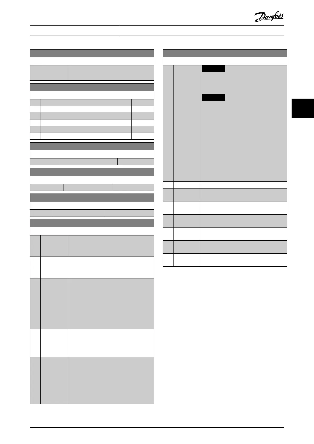
1-82 Min Speed for Function at Stop [Hz]
Range: Function:
0 Hz* [0 - 20 Hz] Set the output frequency at which to
activate parameter 1-80 Function at Stop.
1-83 Precise Stop Function
Option: Function:
[0] * Precise ramp stop
[1] Counter stop with reset
[2] Counter stop without reset
[3] Speed compensated stop
[4] Speed compensated counter stop with reset
[5] Speed compensated counter stop without reset
1-84 Precise Stop Counter Value
Range: Function:
100000* [0 - 999999999 ]
1-85 Precise Stop Speed Compensation Delay
Range: Function:
10 ms* [0 - 100 ms]
1-88 AC Brake Gain
Range: Function:
1.4* [1.0 - 2.0 ]
1-90 Motor Thermal Protection
Option: Function:
[0]
*
No
protection
Continuously overloaded motor, when no
warning or trip of the frequency converter is
required.
[1] Thermistor
warning
Activates a warning when the connected
thermistor or KTY Sensor in the motor reacts
on a motor overtemperature.
[2] Thermistor
trip
Stops (trips) the frequency converter when
the connected thermistor or KTY Sensor in
the motor reacts on a motor overtem-
perature.
The thermistor cut out value must be >3 kΩ.
Integrate a thermistor (PTC sensor) in the
motor for winding protection.
[3] ETR warning
1
Calculates the load when set-up 1 is active,
and activates a warning in the display when
the motor is overloaded. Program a warning
signal via 1 of the digital outputs.
[4] ETR trip 1 Calculates the load when set-up 1 is active,
and stops (trips) the frequency converter
when the motor is overloaded. Program a
warning signal via 1 of the digital outputs.
The signal appears in the event of a warning
and if the frequency converter trips (thermal
warning).
1-93 Thermistor Source
Option: Function:
NOTICE
This parameter cannot be changed
while the motor is running.
NOTICE
Set the digital input to [0] PNP - Active
at 24 V in parameter 5-00 Digital I/O
Mode.
Select the input to which the thermistor (PTC
sensor) should be connected. An analog
input option [1] Analog Input 53 or [2] Analog
Input 54 cannot be selected if the analog
input is already in use as a reference source
(selected in parameter 3-15 Reference 1 Source,
parameter 3-16 Reference 2 Source, or
parameter 3-17 Reference 3 Source.
[0] * None
[1] Analog
Input 53
[2] Analog
Input 54
[3] Digital input
18
[4] Digital input
19
[5] Digital input
32
[6] Digital input
33
Parameter Descriptions Programming Guide
MG07C102 Danfoss A/S © 12/2015 All rights reserved. 39
4 4

 Loading...


