4-21 Speed Limit Factor Source
Select an analog input for scaling the settings in
parameter 4-19 Max Output Frequency 0–100% (or inverse). The
signal levels corresponding to 0% and 100% are dened in the
analog input scaling, for example parameter group 6-1* Analog
Input 1. This parameter is only active when
parameter 1-00 Conguration Mode is in torque mode.
Option: Function:
[4] Analog in 53 inv
[6] Analog in 54
[8] Analog in 54 inv
4-22 Break Away Boost
Option: Function:
[0] * O
[1] On The frequency converter provides higher current than
normal current levels to enhance breakaway-torque
capacity.
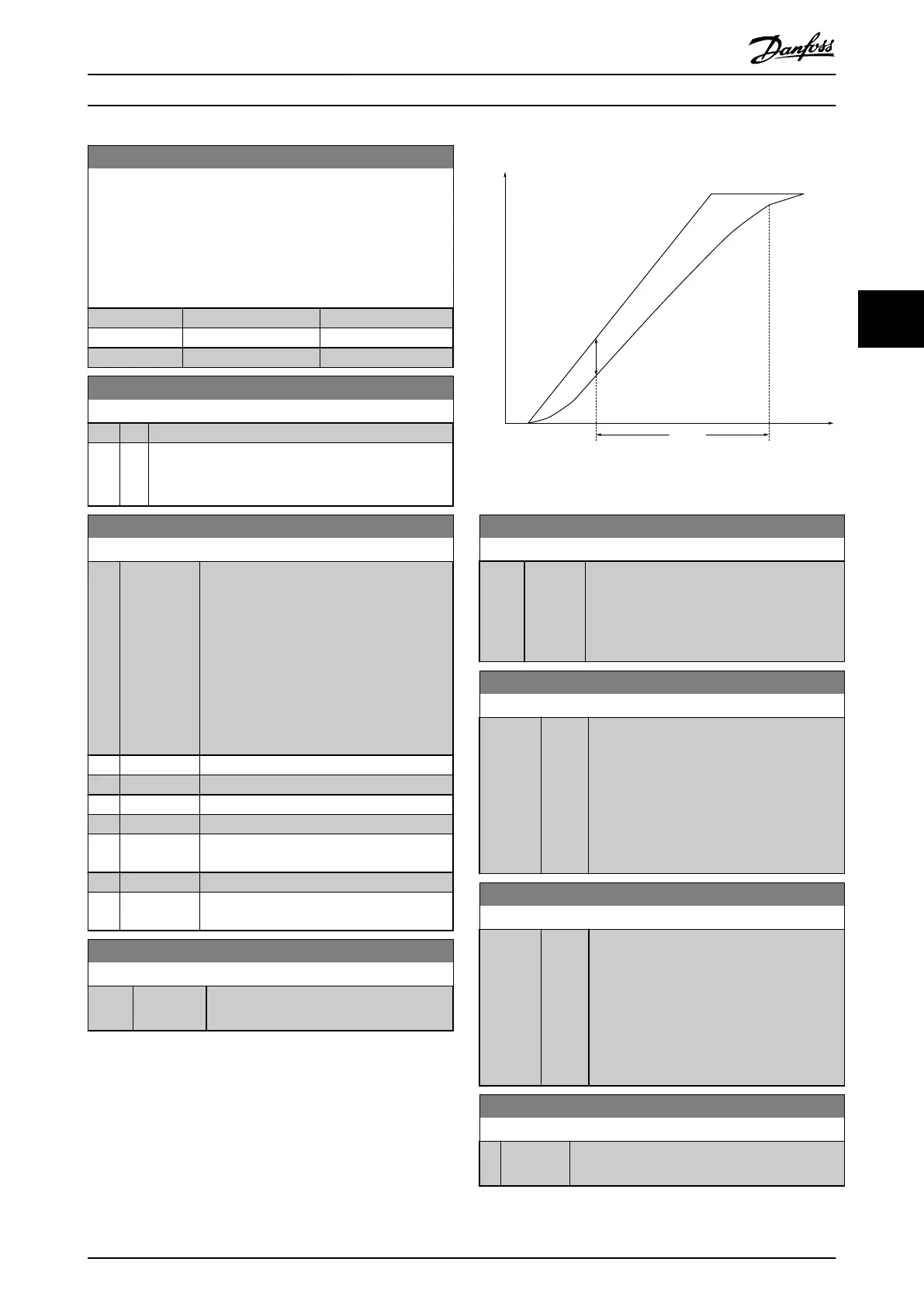
4-30 Motor Feedback Loss Function
Option: Function:
This function is used to monitor consistency
in the feedback signal, that is, if the feedback
signal is available. Select the action of the
frequency converter if a feedback fault is
detected. The selected action takes place
when the feedback signal diers from the
output speed by the value set in
parameter 4-31 Motor Feedback Speed Error
for longer than the value set in
parameter 4-32 Motor Feedback Loss Timeout.
[0] * Disabled
[1] Warning
[2] Trip
[3] Jog
[4] Freeze
Output
[5] Max Speed
[6] Switch to
Open Loop
4-31 Motor Feedback Speed Error
Range: Function:
20 Hz* [0 - 50 Hz] Select the maximum allowed error in speed
(output speed versus feedback).
Time
[sec]
Speed
[rpm]
n
calc
n
actual
P 4-32
130BA221.10
P 4-31
Illustration 4.8 Motor Feedback Speed Error
4-32 Motor Feedback Loss Timeout
Range: Function:
0.05 s* [0 - 60
s]
Set the timeout value allowing the speed
error set in parameter 4-31 Motor Feedback
Speed Error to be exceeded before enabling
the function selected in parameter 4-30 Motor
Feedback Loss Function.
4-40 Warning Freq. Low
Range: Function:
Size
related*
[ 0 -
400
Hz]
Use this parameter for setting a lower limit
for the frequency range. When the motor
speed drops below this limit, the display
reads Speed low. Warning bit 10 is set in
parameter 16-94 Ext. Status Word. Output relay
can be congured to indicate this warning.
LCP warning light is not lit when the limit set
is reached.
4-41 Warning Freq. High
Range: Function:
Size
related*
[ 0 -
400
Hz]
Use this parameter for setting a higher limit
for the frequency range. When the motor
speed exceeds this limit, the display reads
Speed high. Warning bit 9 is set in
parameter 16-94 Ext. Status Word. Output relay
can be congured to indicate this warning.
LCP warning light is not lit when the limit set
is reached.
4-42 Adjustable Temperature Warning
Range: Function:
0* [ 0 - 255 ] Use this parameter to set the motor temperature
limit.
Parameter Descriptions Programming Guide
MG07C102 Danfoss A/S © 12/2015 All rights reserved. 49
4 4
 Loading...


