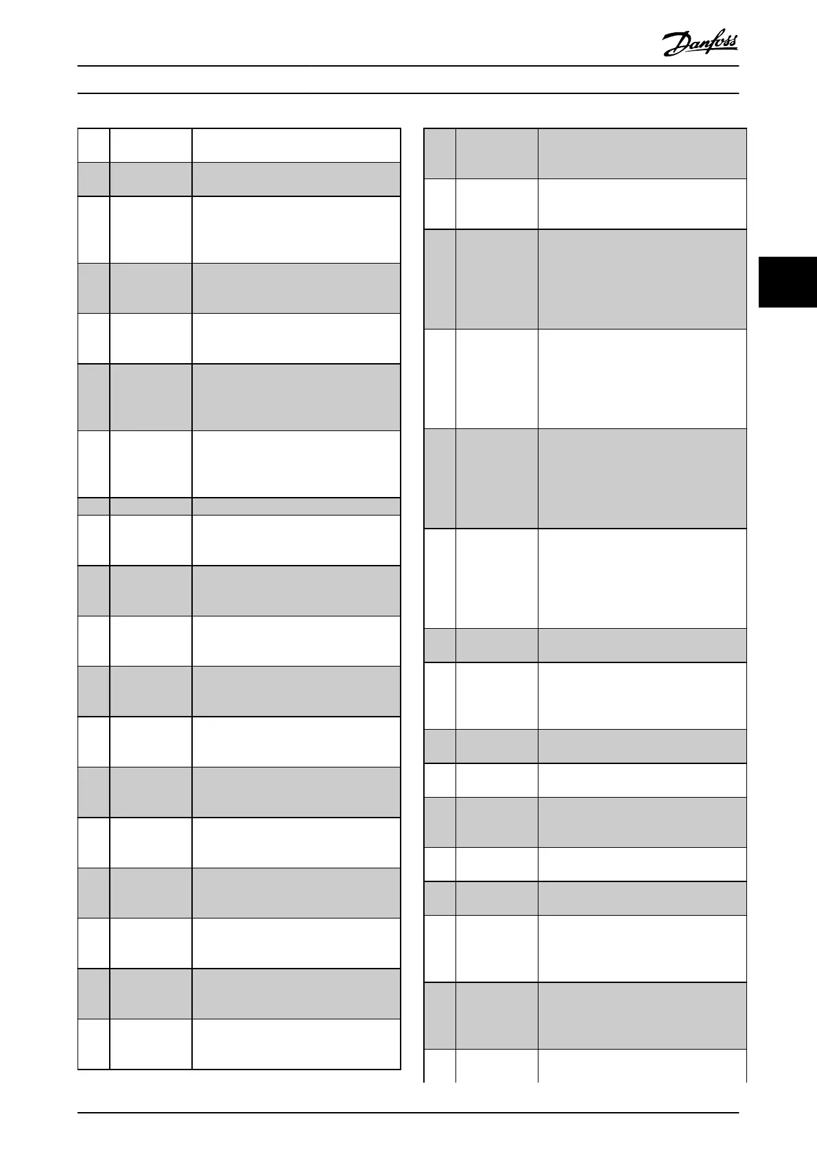
[36] Control word
bit 11
[37] Control word
bit 12
[40] Out of ref
range
This option is active when the actual
speed is outside the settings in
parameter 4-52 Warning Speed Low to
parameter 4-55 Warning Reference High.
[41] Below
reference low
This option is active when the actual
speed is below the speed reference
setting.
[42] Above
reference high
This option is active when the actual
speed is above the speed reference
setting.
[45] Bus Ctrl Controls output via eldbus. The state of
the output is set in parameter 5-90 Digital
& Relay Bus Control. The output state is
retained in the event of eldbus timeout.
[46] Bus Ctrl On at
timeout
Controls output via eldbus. The state of
the output is set in parameter 5-90 Digital
& Relay Bus Control. When bus timeout
occurs, the output state is set high (On).
[55] Pulse output
[56] Heat sink
cleaning
warning, high
[60] Comparator 0 See parameter group 13-1* Comparators.
If comparator 0 is evaluated as TRUE, the
output goes high. Otherwise, it is low.
[61] Comparator 1 See parameter group 13-1* Comparators.
If comparator 1 is evaluated as TRUE, the
output goes high. Otherwise, it is low.
[62] Comparator 2 See parameter group 13-1* Comparators.
If comparator 2 is evaluated as TRUE, the
output goes high. Otherwise, it is low.
[63] Comparator 3 See parameter group 13-1* Comparators.
If comparator 3 is evaluated as TRUE, the
output goes high. Otherwise, it is low.
[64] Comparator 4 See parameter group 13-1* Comparators.
If comparator 4 is evaluated as TRUE, the
output goes high. Otherwise, it is low.
[65] Comparator 5 See parameter group 13-1* Comparators.
If comparator 5 is evaluated as TRUE, the
output goes high. Otherwise, it is low.
[70] Logic Rule 0 See parameter group 13-4* Logic Rules. If
logic rule 0 is evaluated as TRUE, the
output goes high. Otherwise, it is low.
[71] Logic Rule 1 See parameter group 13-4* Logic Rules. If
logic rule 1 is evaluated as TRUE, the
output goes high. Otherwise, it is low.
[72] Logic Rule 2 See parameter group 13-4* Logic Rules. If
logic rule 2 is evaluated as TRUE, the
output goes high. Otherwise, it is low.
[73] Logic Rule 3 See parameter group 13-4* Logic Rules. If
logic rule 3 is evaluated as TRUE, the
output goes high. Otherwise, it is low.
[74] Logic Rule 4 See parameter group 13-4* Logic Rules. If
logic rule 4 is evaluated as TRUE, the
output goes high. Otherwise, it is low.
[75] Logic Rule 5 See parameter group 13-4* Logic Rules. If
logic rule 5 is evaluated as TRUE, the
output goes high. Otherwise, it is low.
[80] SL Digital
Output A
See parameter 13-52 SL Controller Action.
The output goes high whenever the
smart logic action [38] Set dig. out. A high
is executed. The output goes low
whenever the smart logic action [32] Set
dig. out. A low is executed.
[81] SL Digital
Output B
See parameter 13-52 SL Controller Action.
The input goes high whenever the smart
logic action [39] Set dig. out. B high is
executed. The input goes low whenever
the smart logic action [33] Set dig. out. B
low is executed.
[82] SL Digital
Output C
See parameter 13-52 SL Controller Action.
The input goes high whenever the smart
logic action [40] Set dig. out. C high is
executed. The input goes low whenever
the smart logic action [34] Set dig. out. C
low is executed.
[83] SL Digital
Output D
See parameter 13-52 SL Controller Action.
The input goes high whenever the smart
logic action [41] Set dig. out. D high is
executed. The input goes low whenever
the smart logic action [35] Set dig. out. D
low is executed.
[160] No alarm The output is high when no alarm is
present.
[161] Running
reverse
The output is high when the frequency
converter is running counterclockwise
(the logical product of the status bits
Running AND Reverse).
[165] Local reference
active
[166] Remote ref
active
[167] Start command
active
The output is high when there is an
active start command, and no stop
command is active.
[168] Drive in hand
mode
The output is high when the frequency
converter is in hand-on mode.
[169] Drive in auto
mode
The output is high when the frequency
converter is in auto-on mode.
[170] Homing
Completed
The homing operation is completed. This
option is only eective when
parameter 37-00 Application Mode is set to
[2] Position Control.
[171] Target Position
Reached
The target position is reached. This option
is only eective when
parameter 37-00 Application Mode is set to
[2] Position Control.
[172] Position
Control Fault
A fault occurred in the positioning
process. Refer to parameter 37-18 Pos. Ctrl
Parameter Descriptions Programming Guide
MG07C102 Danfoss A/S © 12/2015 All rights reserved. 55
4 4

 Loading...


