EasyManua.ls Logo

Data Aire MINI DATA ALARM PROCESSOR II User Manual

Data Aire MINI DATA ALARM PROCESSOR II
28 pages
To Next Page IconTo Next Page
To Previous Page IconTo Previous Page
Page #6 background image
MINI DATA ALARM PROCESSOR II
The MINI-DAP II control panel is designed for Data Aire Ceiling systems with one or two cooling stages, one heating
stage and a humidifier. This microprocessor based control offers innovative features and “state of the art” technology.
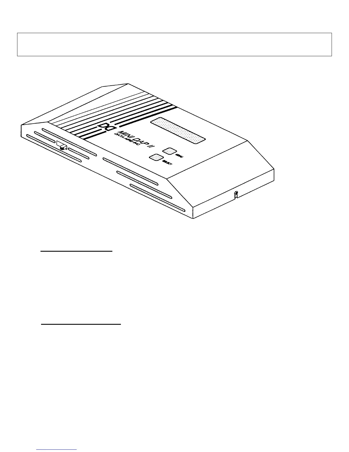
Figure 1: Mini-Dap II Panel
Design Features
Microprocessor based dual layer board
design
16 characters liquid crystal display (LCD)
Panel mounted temperature and humidity
sensor are standard
Nonvolatile memory storage for all
programmed settings and alarm history (5
latest alarms)
Printed circuit board mounted audio alarm
Five control outputs for fan, cooling stage 1,
cooling stage 2, heat, humidifier
Five alarm inputs with three selectable
messages
Optional plug-in remote alarm contact
Software Features
Setpoint deviation control logic
Selectable night setback and on/off
functions provide an economical control
solution
Adjustable system reaction time (Adjustment
rate)
All settings are programmed using menu
driven soft-touch keys
Adjustable temperature and humidity
deadband
°C to °F conversion
Two level passwords for menus access
Calibration offset for temperature and
humidity sensor
Manual diagnostics for components
troubleshooting
REV 8/03
4

Table of Contents

Question and Answer IconNeed help?

Do you have a question about the Data Aire MINI DATA ALARM PROCESSOR II and is the answer not in the manual?

Data Aire MINI DATA ALARM PROCESSOR II Specifications

General IconGeneral
BrandData Aire
ModelMINI DATA ALARM PROCESSOR II
CategorySecurity System
LanguageEnglish

Summary

Introduction

Protective & Safety Features

Describes the enclosure, power protection, and signal isolation features ensuring safe and reliable operation.

Installation

Installation and Wiring

Covers the physical mounting and electrical connection procedures for the MINI-DAP II panel and its components.

Programming and Selections

Menu Operations and Settings

Guides the user through accessing and modifying various system parameters, setpoints, and configurations via the menu system.

Password A Configuration

Details setting and managing the first level of password protection for system access and programming.

Temperature Setpoint Adjustment

Explains how to set and adjust the desired room temperature for cooling and heating operations.

Humidity Setpoint Adjustment

Guides users on setting and modifying the desired room humidity levels for humidification and dehumidification.

Password B Configuration

Details setting and managing the second level of password protection for enhanced system security.

Setup Cooling Setback

Adjusts the cooling setpoint upward during unoccupied periods for energy savings.

Setback Heating Setpoint

Adjusts the heating setpoint downward during unoccupied periods for energy savings.

Setup Dehumidification Setback

Adjusts the dehumidification setpoint upward during unoccupied periods.

Setback Humidification Setpoint

Adjusts the humidification setpoint downward during unoccupied periods.

High Temperature Limit Setting

Defines the upper limit for temperature that triggers a high-temperature alarm.

Low Temperature Limit Setting

Defines the lower limit for temperature that triggers a low-temperature alarm.

High Humidity Limit Setting

Defines the upper limit for humidity that triggers a high-humidity alarm.

Manual Diagnostic Program

Control Logic

Occupied or Normal Mode Logic

Details the operational logic for Evaporator Fan, Cooling, Heating, Humidification, and Dehumidification in occupied mode.

Setback/Up Mode Logic

Explains the operational logic for Cooling, Heating, Humidification, and Dehumidification in unoccupied periods of setback/up schedules.

Alarms Logic

High Temperature Alarm

Indicates when return air temperature exceeds the high temperature limit setting.

Low Temperature Alarm

Indicates when return air temperature falls below the low temperature limit setting.

High Humidity Alarm

Indicates when return air humidity exceeds the high humidity limit setting.

Low Humidity Alarm

Indicates when return air humidity falls below the low humidity limit setting.

Firestat Alarm

Terminates all functions immediately when return air temperature exceeds the firestat limit.

Temperature Sensor Fail Alarm

Indicates a fault or failure in the temperature sensor, potentially affecting other alarms.

Humidity Sensor Fail Alarm

Indicates a fault or failure in the humidity sensor, locking out humidification/dehumidification.

High Pressure 1 Alarm (HI PRES C1)

Signals a high-pressure condition in the first compressor, shutting it down.

High Pressure 2 Alarm (HI PRES C2)

Signals a high-pressure condition in the second compressor, shutting it down (for dual systems).

Smoke Alarm

Optional alarm activated by a smoke detector, shutting down all unit functions.

Troubleshooting

Related product manuals