REV 8/03
14
4- TMP,HUM,AD CAL
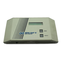
Press select button to display the temperature
sensor raw value and its calibration offse,t which
is programmed on menu #31. Press select
button to display the humidity sensor raw value
and its calibration offset, which is programmed
on menu #35. Press select button again, panel
will display the reference voltage of the sensors
(temperature and humidity): REF: 5.000 (VDC).
Press select button to display the voltage
reading (raw value) across sensors.
Note: the offset is the amount of calibration
required for a true reading of room condition.
Press the menu button to go to the next test.
5- ALARM INPUT
Press select button to display the 24 VAC alarm
inputs on the terminal strip of the panel: P 09,
10, 11,12,13. The connector terminal number
indicates the alarm input is on, a dash mark (--)
means the alarm input is off. The alarm inputs
(terminal numbers) are as follows:
9. High condensate alarm
10. No air flow alarm
11. Optional input #1 (may be set for Hi
press C1 for single compressor)
12. Optional input #2 (may be set for Hi
press C2 for dual compressor)
13. Optional input #3
Press menu button to go back to test 1.
To go back to the normal operation, Turn panel
off, wait 5 seconds then turn the panel back on.
Panel will go thru the self-test then unit will come
back on.
C
ontrol Logic
This control panel can be programmed in two different types of operation:
1. Continuous operation, no setback or schedule. This operation is normally applied to a
computer room or equipment room. This requires the menu #13 on the MINI-DAP II panel
set to “N”. the operational logic of this mode is the same as the logic of the OCCUPIED
mode. See below logic for details.
2. Setback/up or On/Off operation. This requires that menu #13 is set to “Y” and the seven
days schedules are set on menu #20 thru #26. See Menus setting for details. This operation has two
periods: OCCUPIED period and UNOCCUPIED period. See below logic for details.
Important note:
1. If menu #13- DAY SCHEDULE is set for “Y”, the time-of-day schedule setting for occupied and
unoccupied period must be set on menu #20 to #26. If they are left at “N/C”, the control panel will
operate as it is in the occupied period at all time.
2. Mini-DAP II panel does not have a real time clock with backup battery therefore the date and time
must be reset every time the panel loses power, otherwise the panel will stay in the same mode as
last time it is turned off and “TIME NOT SET” message will appear.
Occupied or Normal mode
When unit is in the “OCCUPIED” mode or normal operation, the MINI-DAP II will operate in the
following control logic:
EVAPORATOR FAN
The blower will operate based on the setting of menu #43-FAN MODE: AUTO OR CONT
AUTO: fan comes on when unit calls for cooling, heating, dehumidification and
humidification. It goes off in one minute when no functions are called for.
CONT: fan runs continuously during the occupied mode even when no functions are needed.
OCCUPIED COOLING LOGIC
1. 5 minutes delay between start to start of the compressor (anti short cycle delay).
2. 2 minutes delay between stop to start of the same compressor.
3. Compressor sequences as follows:
COOL 1 ON AT TEMPERATURE SETPOINT + TEMPERATURE DEADBAND
COOL 2 ON AT TEMPERATURE SETPOINT + TEMPERATURE DEADBAND + .3°F (IF EXISTS)

 Loading...