Technical Specifications
26
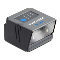
GRYPHON™ I GFS4500
RS-232 Electrical Connections (GFS4550 only)
Default configuration is RS-232: 9600, 8, N, 1, no hand-
shaking, ACK/NAK disabled.
9-PIN CONNECTOR
1 Trigger
Trigger signal input (see Figure 5
and Figure 6 on next page)
2 TX
Transmit Data (output from
scanner)
3 RX Receive Data (input to scanner)
4 NC Not connected
5 GND Ground
6 VCC +5Vdc
7 CTS Clear To Send (input to scanner)
8 RTS
Request To Send (output from
scanner)
9 DIGITAL OUTPUT
Output signal (see Figure 8 and
Figure 9)

 Loading...