Connecting the Base Station
Quick Reference Guide 9
Many stand alone connections can operate in the same physi-
cal area without interference, provided all readers and cradles
in the system have different addresses.
Using the BC40xx™ Radio Base
Radio Base LEDs
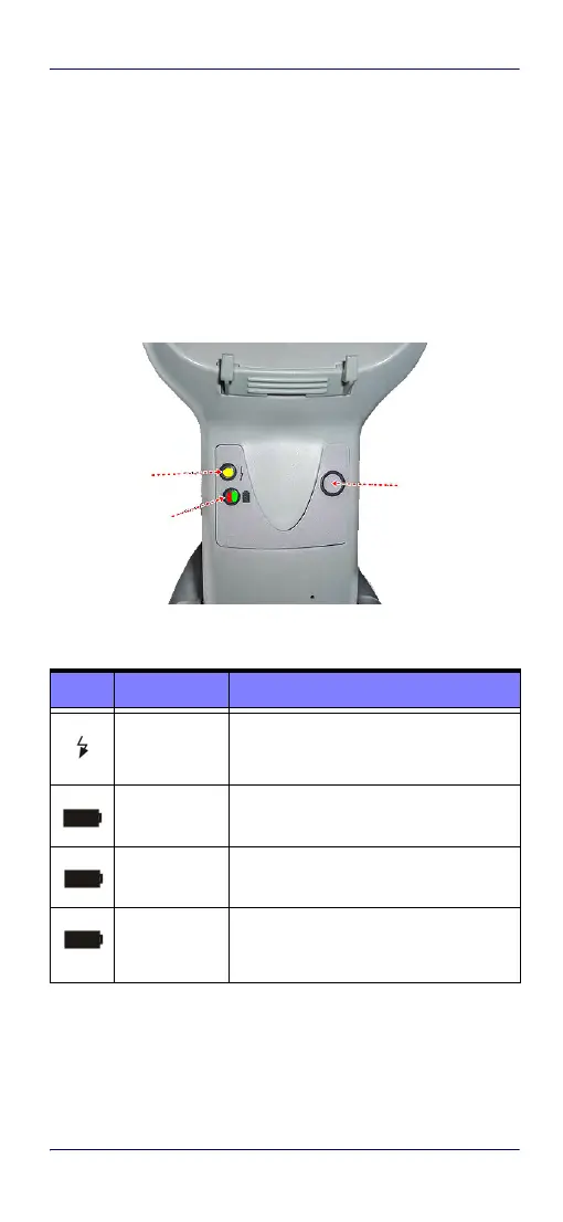
LEDs on the Gryphon Base provide information about the
Base as well as battery charging status, as shown in
Figure 13
.
Figure 13. Gryphon Base LEDs
Table 1. Radio Base LEDs
The button can be used to force device connection via the Da-
talogic Aladdin Software tool and for paging the scanner when
it is activated. Refer to the Gryphon I 44XX Product Refer-
ence Guide (PRG) for a more detailed explanation.
LED STATUS
Power on /
Data
Yellow On = Base is powered
Yellow Blinking = Base receives data and
commands from the Host or the Reader.
Charging Red On = the Battery is charging.
Charge com-
pleted
Green On = the Battery is completely
charged.
Charging +
Charge com-
pleted
Red and Green Blinking together = the
Reader is not correctly placed onto the
Base.
YELLOW LED
RED LED /
GREEN LED
BUTTON

 Loading...