Do you have a question about the Datalogic PowerScan RF and is the answer not in the manual?
Provides an overview of the manual's contents and the system.
Lists other available manuals and how to obtain them, including software.
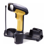
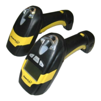
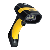
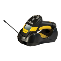
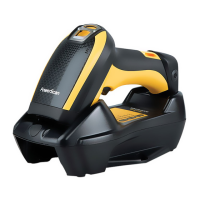
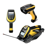
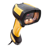
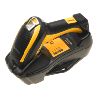
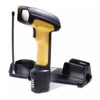
Illustrates the labels and identifies parts of the PowerScan RF scanner.
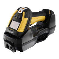
Identifies components and labels of the PowerScan RF Base Station.
Warns against staring into laser beam and attempting repairs, and opening optics cavity.
Lists items to check after unpacking the Base Station.
Outlines basic steps for setting up the RF scanner system.
Instructions on how to insert and remove the scanner battery.
Describes how to check scanner functionality by scanning sample bar codes.
Details steps for connecting the Base Station to the host system.
Explains how to link a scanner to a Base Station using the ID bar code.
Describes how to confirm communication between scanner and Base Station.
Introduces topics covered in this section related to system usage.
Provides advice on maximizing rechargeable battery lifespan.
Information on the proper disposal of NiMH batteries.
Describes the optional Four Station Charger accessory for batteries.
Defines a "mil" as 0.001 inches for bar code element width.
Diagram showing depth of field for High Density scanner models.
Diagram showing depth of field for Long Range scanner models.
Diagram showing depth of field for Extra Long Range scanner models.
Details the functions of the scanner's green LED indicator.
Details the functions of the scanner's yellow LED indicator.
Lists various beeper indications and their meanings.
Lists speaker indications like Transmission Error Beep, Link Beep, Unlink Beep.
Instructions for securing the Base Station horizontally on a surface.
Steps for mounting the Base Station using mounting flanges.
Instructions for attaching the Base Station using provided adhesive tape.
Details how to mount the Base Station vertically on a wall.
Lists methods for configuring scanner and Base Station units.
Discusses scanner programming methods, including software and bar codes.
Explains Base Station configuration via scanner programming.
Describes how to enter and use programming mode with bar codes.
Details the steps for a typical scanner programming session.
Explains different sequences for scanning programming bar codes.
Explains how features are applicable to scanner, Base Station, or both.
Instructions for scanning bar codes to reset scanner/Base Station to factory defaults.
Details how to configure scanner and Base Station for matching host terminal interfaces.
Instructions for activating the Universal Wedge interface.
Lists common terminal/keyboard types and their IDs.
Provides bar codes for entering numbers for Universal Wedge configuration.
Discusses scanner beeper behavior unique to RF models.
Configures when the scanner will beep for good read, ACK, or transmission errors.
Sets the volume level for ACK, transmission error, link, and unlink beeps.
Sets the frequency for the ACK beep to distinguish from the good read beep.
Sets the duration of the ACK beep sound.
Allows adjustment of radio signal power for optimal communication.
Selects radio channels to improve communication in noisy RF environments.
Defines the number of retries before a transmission fails.
Sets the time for the Base Station to acknowledge data transmission.
Configures the idle time before the scanner automatically shuts down.
Defines the delay between retrying failed transmissions.
Configures when the Base Station sends Host Acknowledgement (HACK) messages.
Sets the time the scanner waits for a HACK message from the host.
Enables/disables dropping scanner links upon Base Station power reset.
Manages scanner linking by unlinking the oldest inactive scanner when full.
Enables Base Station to share its configuration with linking scanners.
Limits the number of scanners that can be linked to a Base Station.
Allows inclusion of scanner ID with transmitted bar code data.
Enables/disables the flashing green LED for low battery status.
Instructions for cleaning the scanner's scan window and body.
Notes that Base Station requires no routine maintenance, but antenna kits are available.
Mentions availability of replacement kits for Four Station Charger contacts.
Lists reasons and solutions for scanner linking failures.
Lists conditions not covered by the warranty.
Defines Datalogic's liability regarding product defects.
Addresses customer's rights regarding warranty transfer.
Covers responsibility for product loss or damage during transit.
Sample bar code for Code 128 symbology.
Sample bar code for Code 39 symbology.
Sample bar code for Interleaved 2 of 5 symbology.
Sample bar code for Standard 2 of 5 symbology.
Sample bar code for Codabar symbology.
Sample bar code for Code 93 symbology.
Sample bar code for MSI/Plessey symbology.
Sample bar code for UPC-A symbology.
Sample bar code for UPC-A with 2-digit add-on.
Sample bar code for UPC-A with 5-digit add-on.
Sample bar code for UPC-E symbology.
Sample bar code for EAN-8 symbology.
Sample bar code for EAN-13 symbology.
| Brand | Datalogic |
|---|---|
| Model | PowerScan RF |
| Category | Barcode Reader |
| Language | English |