Do you have a question about the Datalogic PowerScan M8300 and is the answer not in the manual?
Provides the primary contact number for assistance and support.
Offers support channels like email and live chat for inquiries.
States that specifications may change without prior notice.
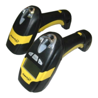
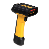
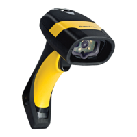
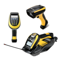
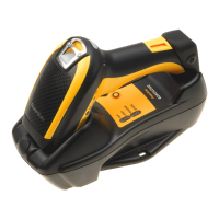
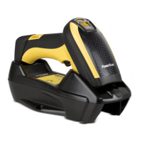
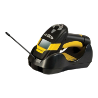
Illustrates the physical components and layout of the scanners.
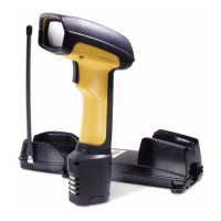
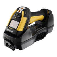
Shows the BC-8000 cradle with key features like LED indicators and scan finder.
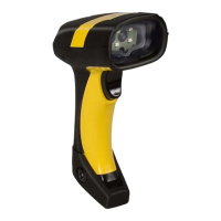
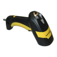
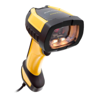
Introduces the Datalogic PowerScan family of industrial laser scanners.
Details how to connect the interface cable to the D8330 reader.
Step-by-step guide for inserting the interface cable correctly.
Explains connecting the interface cable to the BC-80X0 cradle.
Illustrates the physical connection for RS-232 interfaces.
Shows the physical connection for USB interfaces.
Demonstrates the connection for IBM USB POS systems.
Illustrates the physical connection for Wedge interfaces.
Shows the physical connection for Pen Emulation interfaces.
Covers network connectivity options and setups.
Details the connectors for network configurations on the BC-8060 cradle.
Describes the specifications and wiring for multidrop network cables.
Explains how to terminate the network ends using internal jumpers.
Procedures for maintaining the PowerScan M8300 batteries.
Instructions for charging the PowerScan M8300 battery in the cradle.
Details on mounting the BC-80X0 and C-8000 cradles.
Lists the items included in the cradle package for mounting.
Details desktop mounting options using horizontal and inclined bases.
Shows top and bottom views of the horizontal base for mounting.
Steps for setting up the cradle for portable desktop use.
Instructions for installing the cradle for fixed desktop use with adhesive strips.
Details for fixed desktop installation using mounting screws.
Instructions for mounting the cradle on a wall.
Details using adhesive strips for wall mounting.
Details using mounting screws for wall mounting.
Covers different stand-alone system configurations.
Describes a single reader connected to a base station.
Shows multiple readers connected to a single base station.
Illustrates multiple independent stand-alone systems in the same area.
Explains using a C-BOX for fixed scanner networks.
Details multidrop network configurations using STAR-System.
Describes a setup where the Host acts as the master.
Explains a setup where the BC-8060 cradle acts as the master.
Provides diagnostic commands for network troubleshooting.
Outlines different methods for configuring the reader.
Describes how to configure the reader using barcodes.
Explains the use of Aladdin software for configuration.
Details how to copy configuration from one device to another.
Describes configuring the reader via RS-232 strings from the Host.
Guides on selecting the appropriate setup procedure based on the reader model.
Specific setup steps for the PowerScan D8330 reader.
Configuration steps for point-to-point applications.
Configuration for stand-alone M8300 readers with BC-80X0 cradle.
How to associate multiple M-Series readers with a single cradle.
Configuration for M8300 using STAR-Modem in stand-alone mode.
Configuration for M8300 readers with STAR-System devices.
Configuration for BC-8060 cradles in STAR-System networks.
Guides on selecting the appropriate interface for the reader application.
Steps for configuring readers using the USB interface.
Lists available USB interface types like USB-KBD and USB-COM.
How to modify default parameters to meet specific application needs.
Configuration options for the data transmission speed.
Settings for error checking during data transmission.
Configuration for the number of data bits per character.
Settings for the stop bits used in serial communication.
Options for controlling data flow during serial communication.
Protocol for confirming data reception.
Configuration for First-In, First-Out data buffering.
Sets delay between transmitted characters.
Controls trigger behavior based on serial commands.
Configuration options for USB-COM interface.
Handshaking options for USB-COM.
ACK/NACK settings for USB-COM.
FIFO settings for USB-COM.
Delay settings between characters for USB-COM.
Timeout settings for reception on USB-COM.
Selects keyboard layout for USB-KBD interface.
FIFO settings for USB-KBD interface.
Delay between characters for USB-KBD.
Delay between codes for USB-KBD.
Adjusts keyboard input speed for USB.
Selects keyboard layout for Wedge interface.
Controls the behavior of the Caps Lock key.
Enables automatic recognition of Caps Lock status.
Manages Num Lock behavior in conjunction with Alt Mode.
Sets delay between characters for Wedge.
Sets delay between codes for Wedge.
Configures keyboard type and character mapping.
Details the procedure for setting the keyboard type and mapping.
Configures emulation of control characters.
Sets the operational mode for Pen Emulation.
Controls pulse duration for code resolution.
Options for converting codes to Code 39 or Code 128.
Manages white space around barcodes.
Defines signal output and idle levels.
Defines idle signal levels.
Configuration for the RS-485 network.
Sets the baud rate for the network.
Defines the valid address range for slave cradles on the network.
Configures messages for network errors.
Master cradle messages for reception errors.
Sets headers for the master cradle.
Sets terminators for the master cradle.
Configures identifiers for scanned codes.
Allows defining custom identifiers for codes.
Configures header information for transmitted data.
Configures terminator information for transmitted data.
Defines special key sequences for advanced formatting.
Allows adjusting data by adding/subtracting characters.
Defines characters used for field adjustments.
Configures the transmission of code length information.
Allows replacing characters within scanned data.
Includes reader/cradle address in the message.
Defines characters to separate address fields.
Formats timestamp information for hour and date.
Defines characters to separate timestamp fields.
Puts the reader into a low-power sleep state.
Sets the delay before entering sleep state.
Configures how the reading phase is controlled.
Determines control of the reading phase with hardware trigger.
Enables an audible click sound on trigger press.
Sets the reader turn-off time after a trigger press.
Configures the behavior of the flash for software trigger.
Defines how many codes are read per cycle.
Prevents multiple readings of the same code.
Adjusts the volume of beeper signals.
Selects the sound pitch for beeper signals.
Chooses between monotone and bitonal beeper sounds.
Sets the duration of beeper sounds.
Configures the duration of the good read indicator.
Enables or disables the aiming system.
Adjusts beeper volume on the cradle.
Adjusts decoding for imperfectly printed codes.
Manages decoding on small surfaces.
Verifies interdigit spacing for specific codes.
Sets the number of reads needed before accepting a code.
Aids in reading damaged or poorly printed codes.
Automatically configures code families to be read.
Manually configures each code family.
Disables all code families for selection.
Configuration options for EAN/UPC barcodes.
Settings for EAN/UPC without add-on codes.
Settings for EAN/UPC with add-on codes.
Autodiscrimination for EAN/UPC add-on based on prefix.
Selects prefixes for EAN/UPC barcodes with ADD ON.
Choose whether to transmit check digits for EAN/UPC codes.
Options for converting between EAN/UPC barcode types.
Configuration options for 2/5 barcodes.
Configuration options for Code 39 barcodes.
Configuration options for Code 128 barcodes.
Configuration options for Code 93 barcodes.
Configuration options for Codabar barcodes.
Sets code length for Codabar barcodes.
Configuration options for MSI barcodes.
Configuration options for Code 11 barcodes.
Configuration options for Code 16K barcodes.
Configuration options for Code 49 barcodes.
Configuration options for GS1 DataBar barcodes.
Combines two codes based on type and length.
Defines the first code for concatenation.
Defines the second code for concatenation.
Selects the Code ID for the concatenated result.
Sets the timeout for waiting between concatenated codes.
Outlines the steps for defining advanced formatting.
Starts the definition of an advanced format.
Specifies criteria for matching code type.
Specifies criteria for matching code length.
Specifies criteria for matching predefined character strings.
Divides barcode data into multiple fields.
Sets the length and criteria for each code field.
Specifies how Field 1 is defined (separator, match, length, variable).
Specifies how Field 2 is defined (separator, match, length, variable).
Specifies how Field 3 is defined (separator, match, length, variable).
Specifies how Field 4 is defined (separator, match, length, variable).
Specifies how Field 5 is defined (separator, match, length, variable).
Defines the content of the first additional fixed field.
Defines the content of the second additional fixed field.
Configures the order and number of fields to transmit.
Applies standard formatting rules after advanced formatting.
Enables or disables specific advanced formats.
Defines actions when barcode data does not match format criteria.
Sets timeout for transmission between reader and cradle.
Configures how long the reader waits for host messages.
Sets timeout before power-off.
Determines if the reader receives responses from the Host.
Controls beeper feedback for radio responses.
Manages retrying transmission if it fails.
Allows storing codes for later transmission.
Activates blinking LED to locate the reader.
Sets the reader's date and time.
Adjusts the display contrast.
Sets the size of the text on the display.
Controls the display backlight.
Sets the time before the display turns off.
Configures the reader display behavior.
Configures keypad behavior and character mapping.
General display settings for 16-key models.
Settings for the 16-key keypad.
Enables or disables the 16-key keyboard.
Sets timeout for key press confirmation in alpha mode.
Enables/disables audible feedback for key presses.
Assigns functions to programmable keys (F1-F4, Shift).
Defines custom strings to be associated with Function Keys.
Changes mnemonic labels for function keys.
Enables/disables SHIFT key for switching to lower case mode.
Reprograms the SHIFT key for custom functions.
Enables/disables keypad echo in simple data input mode.
Sets date and time for 16-key models.
Adjusts display contrast for 16-key models.
Sets display turn-off time for 16-key models.
Sets timeout for displaying the last scanned code.
Controls backlight for display and keyboard on 16-key models.
Manages screen refresh during keyboard input.
Formats data entered via keypad or barcodes.
Enables/disables specific formatting for keypad and barcode data.
Adds optional header/terminator to barcode data.
Configures terminator for scanner data.
Adds optional header/terminator to keypad data.
Configures terminator for keypad data.
Forces insertion of code identifier specific to DK models.
Forces insertion of code length specific to DK models.
Selects between Simple Data Input and Quantity/Code modes.
Defines the two basic operating modes for the scanner.
Configures the scanner for quantity and code entry.
Defines behavior when the QTY field is left empty.
Sets rules for sending QTY/CODE pairs.
Programs optional intercode delay for quantity mode.
Inserts a separator between QTY/CODE pairs.
Defines how scanned barcodes interact with CODE fields.
Options for overwriting or appending barcode data.
Detailed parameters for RS-232 communication.
Explains hardware and software handshaking protocols.
Describes the ACK/NACK transmission protocol.
Details the First-In, First-Out buffering parameter.
Timeout for ending data reception from Host.
Parameters specific to Pen Emulation.
Sets output pulse duration for code resolution.
Options for code format conversion.
Manages white space before/after barcode bars.
Describes signal level combinations for Pen emulation.
Sets delay between character blocks for Pen Emulation.
Parameters for network configurations.
Defines valid addresses for slave cradles on the network.
Master cradle messages for network errors.
Master cradle messages for reception errors.
Adds master cradle header/terminator to network messages.
Information on formatting data output.
Selects header and terminator based on interface.
Associates keyboard key sequences with special functions.
Example of using special keys as terminators or headers.
Includes reader/cradle address in the message.
Defines characters to separate address fields.
Formats timestamp information for hour and date.
Defines characters to separate timestamp fields.
Manages power consumption to extend battery life.
Puts the reader into a low-power sleep state.
Sets the delay before entering sleep state.
Settings related to reading operations.
Controls reading phase based on trigger signal type.
Enables an audible click sound on trigger press.
Sets the reader turn-off time after a trigger press.
Defines how many codes are read per cycle.
Prevents multiple readings of the same code.
Settings to enhance barcode decoding capabilities.
Adjusts decoding for imperfectly printed codes.
Manages decoding on small surfaces.
Verifies interdigit spacing for specific codes.
Customizes the format of transmitted barcode data.
Sets criteria for matching codes to specific formats.
Radio configuration settings for M8300 series readers.
Sets timeout for transmission between reader and cradle.
Configures how long the reader waits for host messages.
Sets timeout before power-off.
Determines if the reader receives responses from the Host.
Controls beeper feedback for radio responses.
Manages retrying transmission if it fails.
Allows storing codes for later transmission.
Activates blinking LED to locate the reader.
Controls reader display behavior.
Configures how the reader display behaves.
Lists commands for editing reader configuration.
Sets user-defined configuration as default.
Identifies and transmits information about code families.
Commands for copying configurations between devices.
Steps to copy configuration from a master D8330 reader.
Steps to copy configuration from a master M8300 reader.
Steps to copy configuration from a master BC-80X0 cradle.
Default RS-232 and Data Format parameters for POS terminals.
Procedure for upgrading device firmware using Aladdin software.
Display and keypad settings for 16-key models.
Enables/disables specific formatting for keypad and barcode data.
Forces insertion of code identifier specific to DK models.
Forces insertion of code length specific to DK models.
Explains the default message formats for scanner communication.
Extended message formatting for 16-key models.
How scanner command keys send messages to the host.
Command key functions for M8300 scanners with display.
Keypad layout and functions for M8300-DK 16-key model.
Specifications for the PowerScan D8330 model.
Specifications for the PowerScan M8300 model.
Specifications for the M8300-DK 16-key model.
Specifications for BC-80X0 and C-8000 cradles.
System and radio feature details.
Explains LED and beeper indicators for operational status.
Reader start-up status indicators.
Reader configuration status indicators.
Data entry status indicators.
Power status indicators for M8300.
Status indicators for bind, join, copy commands.
| Scanner type | 1D |
|---|---|
| Maximum range | 30 m |
| Read rate (max) | 40 reads/s |
| Yaw reading angle | -60 - 60 ° |
| Decoding standards | GS1 DataBar, Code 16K, Code 49, GS1 DataBar Expanded Stacked, GS1 DataBar Stacked, GS1 DataBar Stacked Omnidirectional |
| Tilt reading angle | -20 - 20 ° |
| Pitch reading angle | -55 - 55 ° |
| Operating time | 240 min |
| Dimensions (WxDxH) | 114 x 69 x 210 mm |
| Bluetooth | No |
| Operating frequency | 910 MHz |
| Input voltage | 10 - 30 V |
| Battery capacity | 2150 mAh |
| Power requirements | 0.33 - 1A |
| Number of reads per charge | 60000 |
| Certification | IP64, China RoHS, EU RoHS, CDRH Class II, IEC 60825-1 Class 2 |
| Keys quantity | 3 keys |
| Product color | Black, Yellow |
| LED indicators | Charging, Power |
| Display resolution | 32 x 96 pixels |
| Storage temperature (T-T) | -20 - 70 °C |
| Operating temperature (T-T) | -20 - 50 °C |
| Operating relative humidity (H-H) | 0 - 90 % |
| Weight | 393 g |
|---|