ELECTRICAL CONNECTIONS
12 STS320
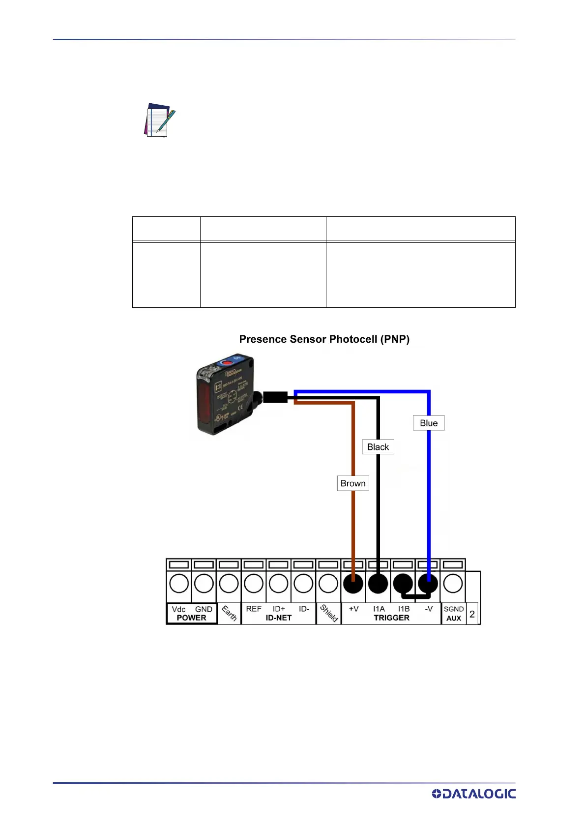
Input Connections for Presence Sensors (provided in the package)
NOTE
The sensors included in the STS320™ have a standard pinout (brown = +Vdc; blue =
GND;
black = switched) and can be connected to the Trigger and Input 2 as shown in the
figures below.
Sensor 1 CBX500 Row 2 Function
brown
black
blue
+V
I1A
I1B
-V (bridge to I1B)
Power Source - External Trigger
External Trigger A (polarity insensitive)
External Trigger B (polarity insensitive)
Power Reference - External Trigger
Figure 12 - Presence Sensor connected to External Trigger
The yellow Trigger LED on the reader is on when the active state of the External Trigger
corresponds to ON.
Power is available directly to the Input Device, independently of the
Power Supply Switch inside the CBX.

 Loading...