EasyManua.ls Logo

Datalogic DS2100N User Manual

Datalogic DS2100N
119 pages
To Next Page IconTo Next Page
Page #1 background imageLoading...
Page #1 background image
DS2100N
Reference Manual

Table of Contents

Other manuals for Datalogic DS2100N

Questions and Answers:

Datalogic DS2100N Specifications

General IconGeneral
TypeLaser Scanner
TechnologyLaser
Protection ClassIP65
Humidity5% to 95% (non-condensing)
Light SourceVisible Laser Diode (650 nm)
InterfacesRS-232
Operating Temperature0°C to 50°C
Power Supply5V DC
Storage Temperature-20°C to 70°C
Drop Specification1.5 m
Resolution0.15 mm / 6 mils

Summary

REFERENCES

Conventions

Defines terms like "User", "Operator", "Device", and "You" for manual clarity.

Reference Documentation

Lists related Datalogic documentation for DS2100N management.

Support Through The Website

Details Datalogic's website services for technical support and product information.

Patents

Lists patents covering the DS2100N product.

SAFETY AND COMPLIANCE NOTICES

Laser Safety

Provides safety information and regulations regarding the laser diode used in the scanner.

FCC Compliance

Outlines compliance with FCC rules for the device's radio frequency emissions.

Power Supply

Specifies requirements for the power supply unit for the DS2100N scanner.

CE Compliance

Addresses CE compliance requirements for the product, particularly regarding interference.

Handling

Provides guidelines for safely handling the scanner to prevent damage.

GENERAL VIEW

DS2100N Component Identification

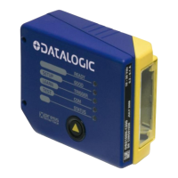
Identifies key components and LEDs on the DS2100N scanner via Figure A.

RAPID CONFIGURATION

Step 1 – Connect the System

Guides on connecting the DS2100N in a Stand Alone configuration for initial setup.

25-pin Connector Pinout

Details the pinout of the 25-pin D-sub connector for power and I/O signals.

Step 2 – Mounting and Positioning

Provides guidance on mounting and positioning the DS2100N for optimal reading.

Step 3 – X-PRESS™ Configuration

Introduces the X-PRESS™ interface for scanner configuration using LEDs and a button.

Auto Learn Procedure

Describes the Auto Learn function for automatic barcode detection and configuration.

Auto Setup (Optional)

Details the Auto Setup function for optimizing reading parameters for specific barcodes.

Reset Scanner to Factory Default

Explains how to reset the scanner to its factory default settings.

Step 4 – Installing Genius™ Configuration

Guides on installing the Datalogic Genius™ software for scanner configuration.

Step 5 – Test Mode

Explains how to use the Test Mode to verify scanner performance and reading capabilities.

Advanced Scanner Configuration

Introduces advanced configuration options for expert users using the Genius™ program.

INTRODUCTION

Product Description

Provides an overview of the DS2100N scanner's features and design.

Indicators

Explains the meaning and function of the five LEDs on the scanner.

ID-NET™ Interface

Introduces the ID-NET™ interface for high-speed scanner interconnection.

Network Setup and Configuration

Details the steps for setting up and configuring an ID-NET™ scanner network.

X-PRESS™ Human Machine Interface

Describes the X-PRESS™ interface for easy installation and maintenance.

Diagnostic Indication

Explains how the STATUS and READY LEDs indicate system failures.

X-PRESS™ Functions

Details how to access functions like Test Mode, AutoLearn, and AutoSetup via the push button.

AutoLearn Function

Describes the process of automatic barcode detection and configuration using AutoLearn.

AutoSetup Function

Explains the AutoSetup function for optimizing reading parameters for specific barcodes.

Model Description

Outlines the different versions of the DS2100N based on resolution, performance, and optics.

Accessories

Lists available accessories for the DS2100N scanner, including mirrors and connection boxes.

INSTALLATION

Package Contents

Lists the items included in the DS2100N scanner packaging.

Mechanical Installation

Provides guidelines and dimensions for physically installing the DS2100N scanner.

Mounting DS2100N

Illustrates how to mount the DS2100N using its mounting bracket for optimal positioning.

Mounting GFC-2020 Mirror

Details the installation of the GFC-2020 accessory lateral output deflection mirror.

Mounting GFC-2100 Mirror

Explains the mounting procedure for the GFC-2100 accessory lateral output deflection mirror.

Mounting GFC-200 Mirror

Describes how to mount the GFC-200 accessory contact reading mirror.

Mounting OM2000N Mirror

Provides instructions for mounting the OM2000N accessory oscillating mirror.

Positioning

Offers suggestions for optimal scanner positioning, focusing on Skew, Tilt, and Pitch angles.

CBX ELECTRICAL CONNECTIONS

Power Supply

Details power supply connections using the CBX100/500 terminal block connectors.

Main Serial Interface

Covers main serial interface options (RS232, RS485) available on the CBX spring clamp terminals.

RS232 Interface

Explains RS232 interface connections for point-to-point communication and hardware handshaking.

RS485 Full-Duplex Interface

Details RS485 Full-Duplex connections for non-polled communication over longer distances.

RS485 Half-Duplex Interface

Describes RS485 Half-Duplex connections for polled communication protocols.

ID-NET™ Interface

Covers the ID-NET™ interface for high-speed scanner interconnection.

ID-NET™ Cables

Specifies cable types and connection guidelines for ID-NET™ networks.

ID-NET™ Response Time

Shows how network response time varies with the number of nodes in an ID-NET™ network.

User Interface - Host

Details PC host interface connections using RS232 on the CBX.

Inputs

Describes the two optocoupled inputs (External Trigger, Input 2) available on the CBX.

Code Verifier

Explains how to configure the scanner as a Code Verifier using Genius™ or input triggers.

Outputs

Describes the two general-purpose outputs (Output 1, Output 2) available on the CBX.

25-PIN CABLE ELECTRICAL CONNECTIONS

Power Supply

Details power supply connections via the 25-pin D-sub connector.

Main Serial Interface

Discusses main serial interface options available on the DS2100N's 25-pin connector.

RS232 Interface

Explains RS232 interface connections using the 25-pin connector and hardware handshaking.

RS485 Full-Duplex Interface

Details RS485 Full-Duplex connections via the 25-pin connector.

RS485 Half-Duplex Interface

Describes RS485 Half-Duplex connections using the 25-pin connector.

ID-NET™ Interface

Covers the ID-NET™ interface connections via the 25-pin connector.

ID-NET™ Cables

Specifies cable types and connection guidelines for ID-NET™ networks using the 25-pin connector.

ID-NET™ Response Time

Illustrates network response time based on nodes and speed for ID-NET™.

Auxiliary RS232 Interface

Details auxiliary RS232 interface connections using the 25-pin connector for configuration.

Inputs

Describes the two optocoupled inputs (External Trigger, Input 2) available on the 25-pin connector.

Outputs

Describes the two general-purpose outputs (Output 1, Output 2) available on the 25-pin connector.

TYPICAL LAYOUTS

Point-to-Point Layout

Illustrates a serial interface point-to-point connection between the scanner and a host.

Fieldbus Interface Point-to-Point Layout

Shows a scanner connected as a slave on a Fieldbus network via a CBX500.

Pass-Through Layout

Describes a layout where devices pass messages through a chain to the host.

ID-NET™ Layouts

Covers ID-NET™ network configurations for data collection from multiple scanners.

Master/Slave Synchronized

Details the ID-NET™ Master/Slave Synchronized network topology.

Master/Slave Multidata

Explains the ID-NET™ Master/Slave Multidata network topology.

RS232 Master/Slave Layout

Illustrates a master/slave connection using RS232 for data collection.

Multiplexer Layout

Shows a scanner network connected to a multiplexer using RS485 half-duplex.

READING FEATURES

Advanced Code Reconstruction (ACR-LITE)

Explains the ACR-Lite technology for reading damaged or low-quality barcodes.

Linear Code Reading

Covers parameters influencing decoding capability in linear barcode reading.

Step-Ladder Mode

Describes the Step-Ladder scanning mode and its formula for effective scans.

Picket-Fence Mode

Explains the Picket-Fence scanning mode and its formula for effective scans.

ACR-Lite Reading Conditions

Lists important conditions and compatibility notes for using ACR-Lite effectively.

Tilt Angle for ACR-Lite

Discusses the significance of tilt angle in the ACR-Lite code reconstruction process.

Advanced ACR Reading Conditions

Provides minimum code height requirements for ACR-Lite based on conveyor speed and code resolution.

Performance

Details scanner performance based on different versions, including resolution and reading distance.

Raster Performance

Discusses performance aspects specific to raster versions of the scanner.

Reading Diagrams

Presents diagrams showing reading performance based on distance and code resolution.

DS2100N-2200 Reading Diagrams

Displays reading diagrams for the DS2100N-2200 (high resolution) model.

DS2100N-1204 Reading Diagrams

Shows reading diagrams for the DS2100N-1204 High Performance model.

DS2100N-2204 Reading Diagrams

Presents reading diagrams for the DS2100N-2204 High Performance model.

MAINTENANCE

Cleaning

Provides instructions for cleaning the laser beam output window for optimal scanner operation.

TROUBLESHOOTING

General Guidelines

Offers general advice for troubleshooting, including wiring attention and parameter references.

Troubleshooting Guide

Lists common problems and their suggested solutions, covering power, errors, and X-PRESS functions.

TECHNICAL FEATURES

GLOSSARY

DECLARATION OF CONFORMITY

Related product manuals