TYPICAL LAYOUTS
71
6
6 TYPICAL LAYOUTS
The following typical layouts refer to system hardware configurations
. Dotted lines in the
figures refer to optional hardware configurations within the particular layout.
These layouts also require the correct setup of the software configuration parameters.
Complete software configuration procedures can be found in the Guide To Rapid
Configuration in the Genius™ Help On Line.
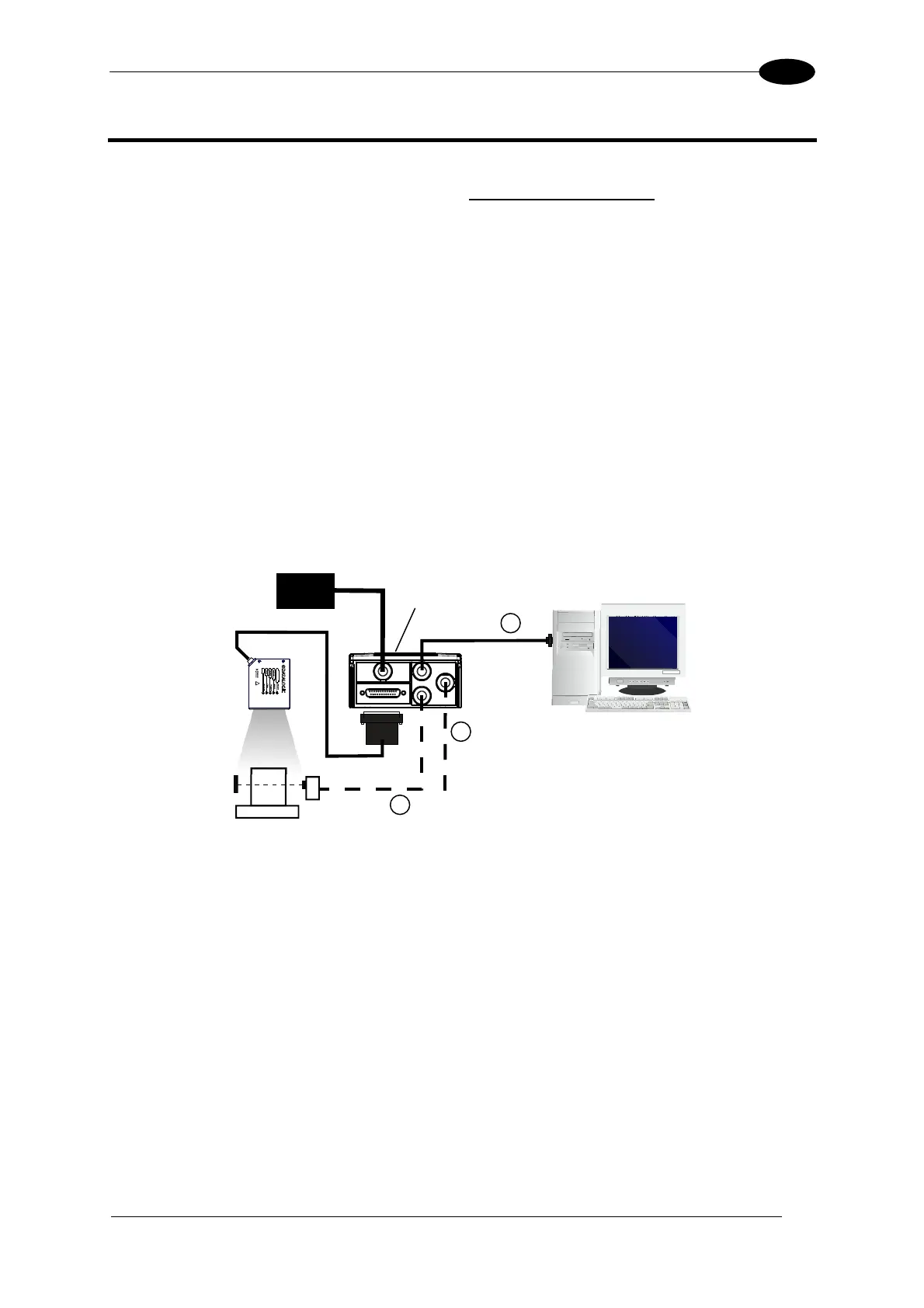
6.1 POINT-TO-POINT
In this layout the data is transmitted to the Host on the main serial interface. A Genius™
based Host Mode programming can be accomplished either through the main interface or the
Auxiliary interface.
In Local Echo communication mode, data is transmitted on the RS232 auxiliary interface
independently from the main interface selection.
When On-Line Operating mode is used, the scanner is activated by an External Trigger
(photoelectric sensor) when the object enters its reading zone.
Figure 85 – Serial Interface Point-to-Point Layout
Terminal
DS2100N
1
2
3
Main Serial Interface (RS232 or RS485 Full-Duplex)
Auxiliary Serial Interface (Local Echo) (RS232)
External Trigger (for On-Line Mode)
Host
PG6000
CBX

 Loading...