INSTALLATION
25
3
3.2 MECHANICAL INSTALLATION
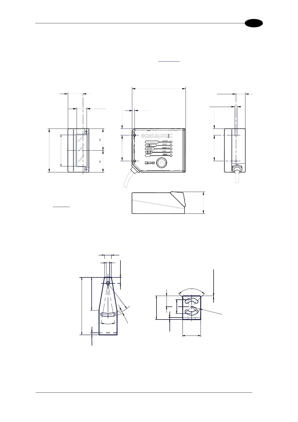
DS2100N can be installed to operate in different positions. The four screw holes (M4 x 5) on
the body of the reader are for mechanical fixture (Figure A
, 3). The diagrams below give the
overall dimensions of the scanner and mounting bracket and may be used for installation.
Refer to par. 3.2.1 and 3.2.4 for correct positioning.
23.3*
0.92
14
0.55
84
3.31
4
0.16
10.3
0.41
40
1.57
0.41
10.3
40
1.57
14.7
0.58
M 4 n° 4
1.29
32.7
mm
inch
68
2.68
46
1.81
* The quote refers to the scan line
Figure 12 – DS2100N Overall Dimensions
9
4.2
7.8
20°
2.5
73
42
R
4
0
4
.
2
90°
30
13.8
17.5
2.5
23
mm
4
.
2
n
°
2
1 x 45° n° 2
Figure 13 – Mounting Bracket Overall Dimensions

 Loading...