25-PIN CABLE ELECTRICAL CONNECTIONS
65
5
5.3.3 ID-NET™ Network Termination
The network must be properly terminated by a 120 Ohm resistor at the first and last scanner
of the network.
5.4 AUXILIARY RS232 INTERFACE
The auxiliary serial interface is used exclusively for RS232 point-to-point connections.
The parameters relative to the aux interface (baud rate, data bits, etc.) as well as particular
communication modes such as LOCAL ECHO can be defined using the Genius™ utility
program or Genius™ based Host Mode Programming installed from the CD-ROM.
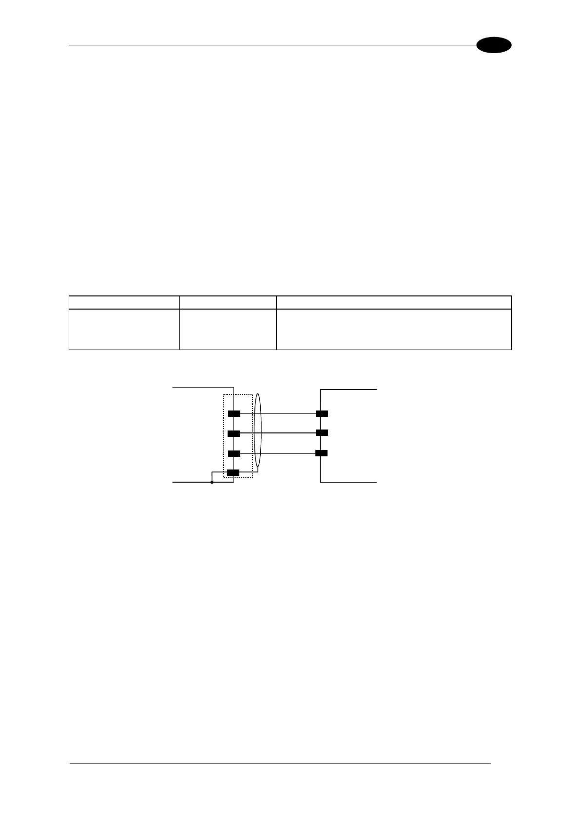
The following pins of the 25-pin connector are used to connect the RS232 auxiliary interface:
Pin Name Function
20 RX Receive Data
21 TX Transmit Data
7 GND Ground
7
GND
GND
TXD
R
20
RXD
T
21
USER INTERFACEDS2100N
1
Chassis
Figure 73 - RS232 Auxiliary Interface Connections

 Loading...