TYPICAL LAYOUTS
75
6
6.3 ID-NET™
The ID-NET™ connection is used to collect data from several scanners to build a multi-point
or a multi-sided reading system; there can be one master and up to 31 slaves connected
together.
The slave scanners are connected together using the ID-NET™ interface. Every slave
scanner must have a ID-NET™ address in the range 1-31.
The master scanner is also connected to the Host on the RS232/RS485 main serial
interface.
For a Master/Slave Synchronized layout the External Trigger signal is unique to the system;
there is a single reading phase and a single message from the master scanner to the Host
computer. It is not necessary to bring the External Trigger signal to all the scanners.
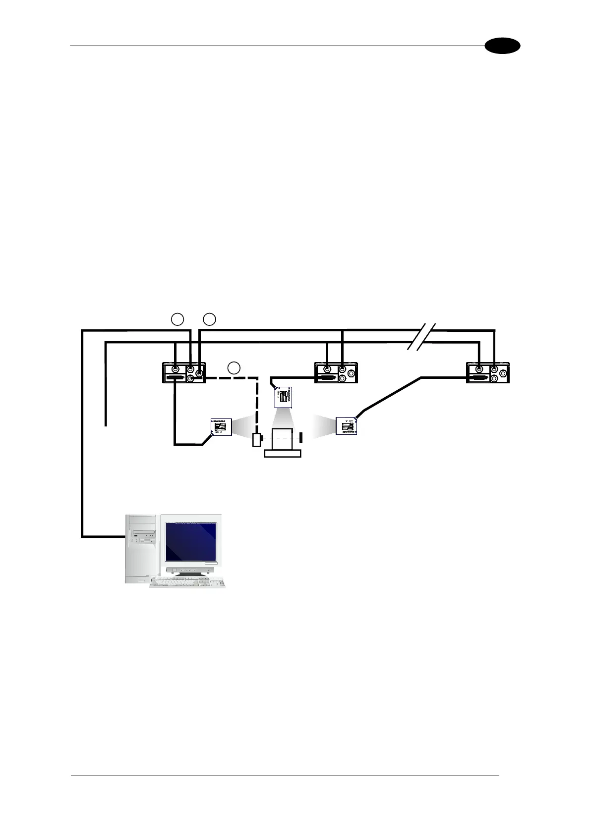
The main, auxiliary, and ID-NET™ interfaces are connected as shown in the figure below.
Figure 89 – ID-NET™ M/S Synchronized Layout
Main Serial Interface (RS232 or RS485)
External Trigger (for On-Line Mode)
ID-NET™ (up to 16 devices - practical limit)
Host
1 3
2
Master
Slave#1 Slave#n
Power

 Loading...