24
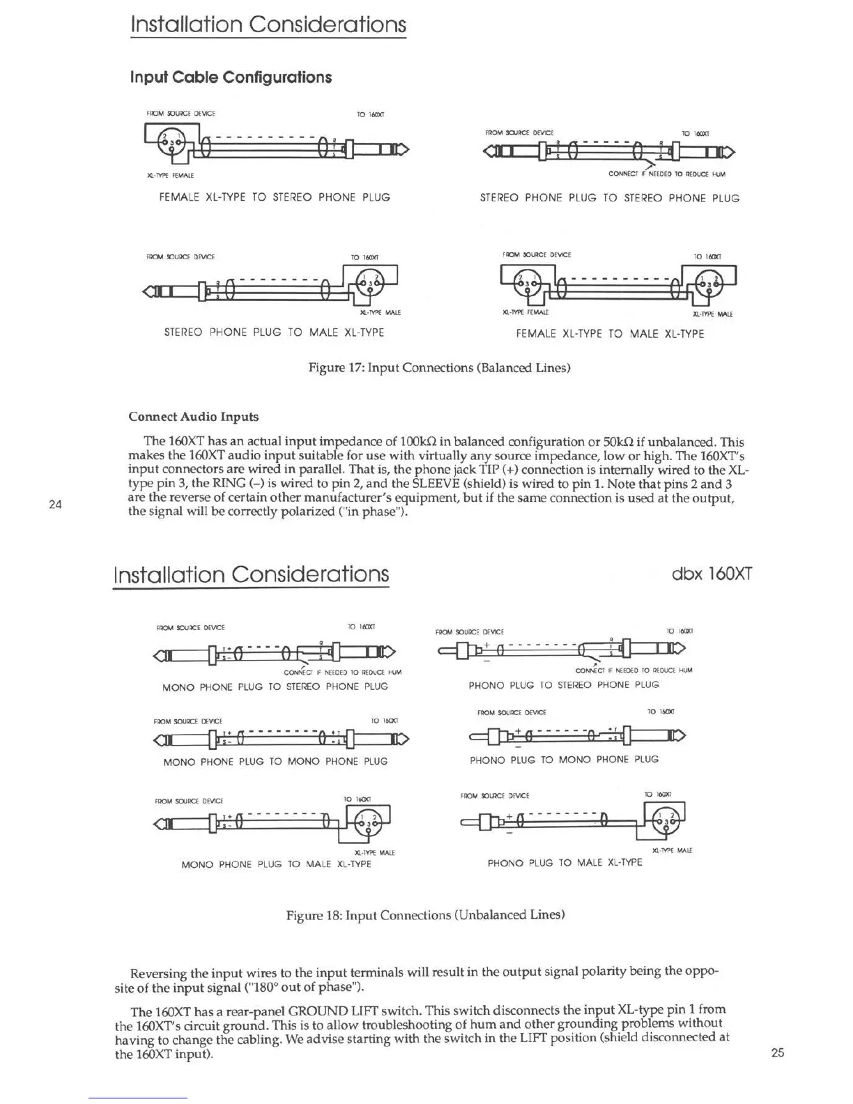
Installation Considerations
Input Cable Configurations
FAOM llOIJllCE DEVlCE
TO leoxt
- - - - - -- - - -
FllOM SOUl!a DEVlCE
TO leoxt
•
<:Di
[) f O -----0 f (] i II:>
>
CONNECT F NEEDED TO !!EDUCE HUM
FEMALE XL-TYPE TO STEREO PHONE PLUG
STEREO PHONE PLUG TO STEREO PHONE PLUG
FROM 9:>Ul!a DEVlCE TO leoxt
FAOM llOIJllCE DEVICE
TO 160XI
2 I
-
-
-
- - - - - - -
• r
l
2
3
I
3
•
I ,
I
JQ.•M'E MALE Xl·TVl'E FEMAlf
Xl-M>E !M l£
STEREO PHONE PLUG TO MALE XL-TYPE
FEMALE XL-TYPE TO MA LE XL-TYPE
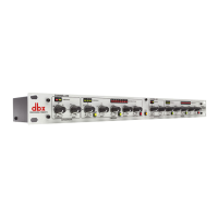
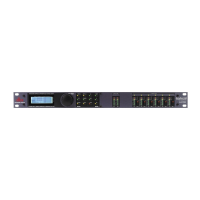
Figure 17: Input Connections (Balanced Lines)
Connect Audio Inputs
The 160XT has an actual input impedance of 100kn in balanced configuration or SOkn if unbalanced. This
makes the 160XT audio input suitable for use with virtually any source impedanc e, low or high . The 160XT's
input connectors are wired in parallel. That is, the phone jack TIP(+) connection is internally wired to the XL-
type pin 3, the RING( -) is wired to pin 2, and the SLEEVE (shield) is wired to pin 1. Note that pins 2 and 3
are the reverse of certain other manufacturer's equipment, but if the same connection is used at the output,
the signal will be correctly polarized ("in phase ").
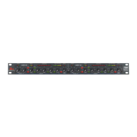
Installation Considerations
FROM 9:>UllCE DEVICE
TO leoxt
<:11 OP!:e··--01 i{] in:>
..,.. __ -l ....
CONN(Cl IF NEEDED 10 REDUCE HIJM
MONO PHONE PLUG TO STEREO PHONE PLUG
FAOM SOURCE DEVCE
TO 160XI
<_::it.__-D ~: o -------· o : ; {].____.r ....... t>
MONO PHONE PLUG TO MONO PHONE PLUG
FllOM SOUl!a DEVICE
TO 160XI
•
--------
I 2
---lJ:i;Ja::::====::u.::µ"t°3o-t-"'
lO.-TVl'E MALE
MONO PHONE PLUG TO MALE XL-TYPE
dbx 160XT
FROM 9:>UllCE DEVICE
TO 160XI
C Q:b + e --------a r {] I It)
- .....
~
CONNECT IF NEEDED 10 l!EDUa HUM
PHONO PLUG TO STEREO PHONE PLUG
FAOM SOURCE DEVICE
TO 160XI
, [J:b: e -----·o, :;{] .... _ .... 1 ..... C>
PHONO PLUG TO MONO PHONE PLUG
FAOM 9:>UllCE DEVlCE
10 160XI
Xl-Tl'l'E W. lE
PHONO PLUG TO MALE XL-TYPE
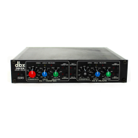
Figure 18: Input Connections (Unbalanced Lines)
Reversing the input wires to the input terminals will result in the output signal polarity being the oppo-
site of the input signal ("180° out of phase ").
The 160XT has a rear-panel GROUND LIFT switch. This switch disconnect s the in~ut XL-type pin J from
the 160XT's circuit ground. This is to allow troubleshooting of hum and other grounding problems without
having to change the cabling. We advise starting with the switch in the LIFT position (shield disconnected at
the 160XT input). 25