6
Rear Panel
A
C
1
INPUT- BA1..ANCEO -OUTI>llf
1
• !O~ ~o©
......
-· _J
81.EE\E QN) fl'IC 1 CIC) - ...., I • - ... I •
•
..,
D
8
G
DE'TB:TOR 81 &tD
N'UT IITRN'PNil
..,..,.
--
• &
-
~~
TAB
DC~
WLTAIEI
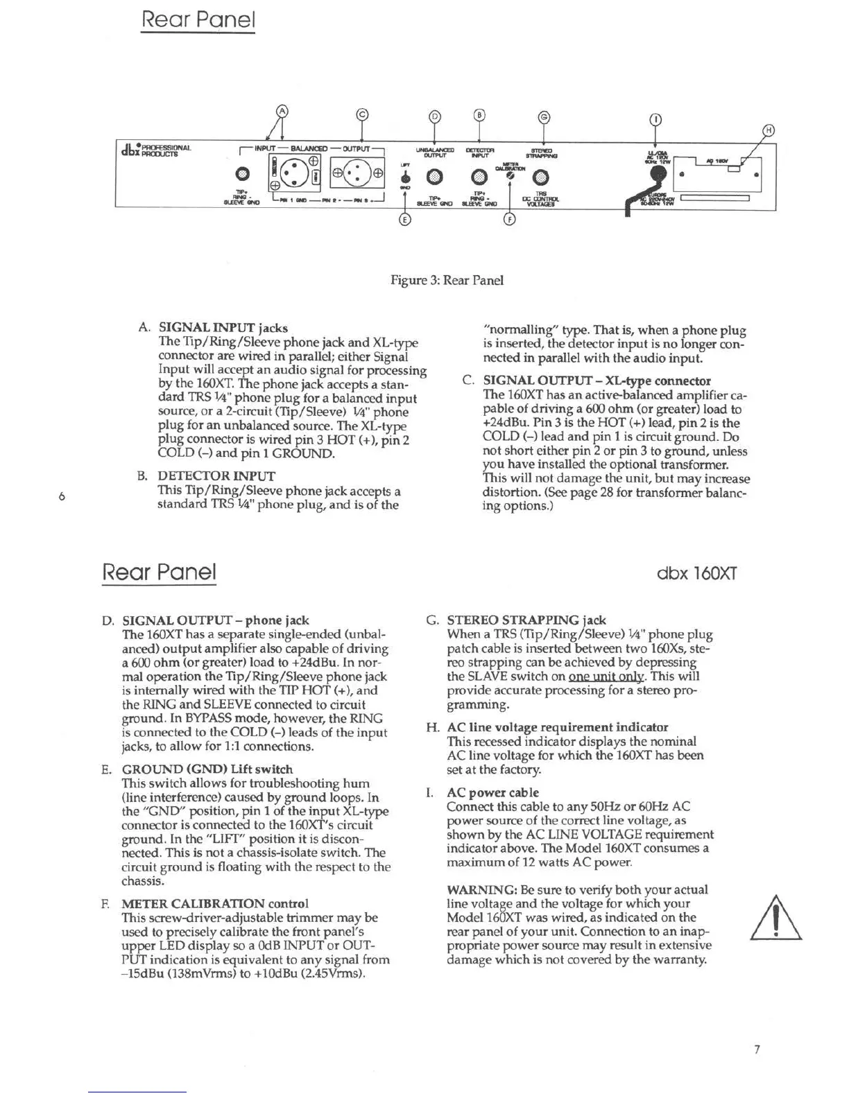
Figure 3: Rear Panel
A. SIGNAL INPUT jacks
The Tip/Ring/Sleeve phone jack and XL-type
connector are wired in parallel; either Signal
Input will accept an audio signa l for processing
by the 160XT. The phone jack accepts a stan-
dard TRS l/4" phone plug for a balanced input
source, or a 2-circuit (Tip/Sleeve) 1/4" phone
plug for an unbalanced source . The XL-type
plug connector is wired pin 3 HOT(+), pin 2
COLD(-) and pin 1 GROUND.
B. DETECTOR INPUT
This Tip/Ring/Sleeve phone jack accepts a
standard TRS ¼" phone plug, and is of the
Rear Panel
"norrnalling" type. That is, when a phone plug
is inserted, the detector input is no longer con-
nected in parallel with the audio input.
C. SIGNAL OUTPUT - XL-type connector
The 160XT has an active-balanced amplifier ca-
pable of driving a 600 ohm (or greater) load to
+24dBu. Pin 3 is the HOT(+) lead, pin 2 is the
COLD(-) lead and pin 1 is circuit ground. Do
not short either pin 2 or pin 3 to ground, unless
you have installed the opt ional transformer.
This will not damage the unit, but may increase
distortion. (See page 28 for transformer balanc-
ing options.)
dbx 160XT
D. SIGNAL OUTPUT - phone jack
G. STEREO STRAPPING jack
The 160XT has a separate single-ended (unbal-
anced) output amplifier also capable of driving
a 600 ohm (or greater) load to +24dBu. In nor-
mal operation the Tip/Ring/Sleeve phone jack
is internally wired with the TIP HOT(+), and
the RING and SLEEVE connected to circuit
ground. In BYPASS mode, however, the RING
is connected to the COLD (-) leads of the input
jacks, to allow for 1:1 connections.
E. GROUND (GND) Lift switch
This switch allows for troubleshooting hum
(line interference) caused by ground loops. In
the "GND" position, pin 1 of the input XL-type
connector is connected to the 160XT's circuit
ground. In the "LIFT" position it is discon-
nected. This is not a chassis-isolate switch. The
circuit ground is floating with the respect to the
chassis.
F. METER CALIBRATION control
This screw-drive r-adjus table trimmer may be
used to precisely calibrate the front panel 's
upper LED display so a OdB INPUT or OUT-
PUT indication is equivalent to any signal from
- lSdBu (138mVrrns) to +lOdBu (2.45Vrrns).
When a TRS (Tip/Ring/Sleeve) ¼" phone plug
patch cable is inserted between two 160Xs, ste-
reo strapping can be achieved by depressing
the SLAVE switch on one unit only. This will
provide accurate processing for a stereo pro-
.
gramrmng.
H. AC line voltage requirement indicator
This recessed indicator displays the nominal
AC line voltage for which the 160XT has been
set at the factory.
I. AC power cable
Connect this cable to any SOHz or 60Hz AC
power source of the correct line voltage, as
shown by the AC LINE VOLTAGE requirement
indicator above. The Model 160XT consumes a
maximum of 12 watts AC power.
WARNING: Be sure to verify both your actual
line voltage and the voltage for which your
Model 160XT was wired, as indicated on the
rear panel of your unit. Connection to an inap-
propriate power source may result in extensive
damage which is not covered by the warranty.
•
7