28
Installation Considerations
Transformer Balanced (OPTIONAL)
POWER
IRANSfOllMER
-- ------1
, ,-o 0-0 0- ,
t ' ' I
t I I
:,,;; S!,•
I I I t
I
1
.().0.().0 t I
------- -·
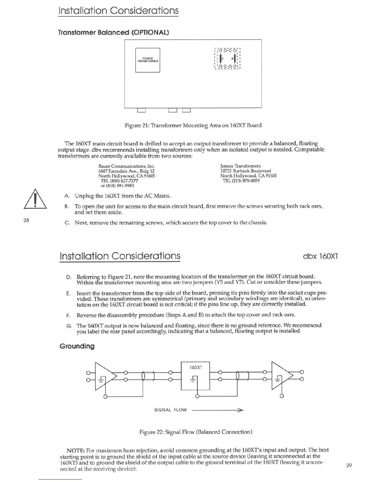
Figure 21: Transformer Mounting Area on 160XT Board
The 160XT main circuit board is drilled to accept an output transformer to provide a balanced, floating
output stage. dbx recommends installing transformers only when an isolated output is needed. Compatable
transformers are currently available from two sources:
Bauer Communications, Inc.
6887 Farmdale Ave., Bldg 12
North Hollywood, CA 91605
TEL (800) 627-7277
or (818) 891-9983
A. Unplug the 160XT from the AC Mains.
Jensen Transformers
10735 Burbank Boulevard
North Hollywood, CA 91601
TEL (213) 876-0059
B. To open the unit for access to the main circuit board, first remove the screws securing both rack ears,
and set them aside.
C. Next, remove the remaining screws, which secure the top cover to the chassis.
Installation Considerations
dbx 160XT
D. Referring to Figure 21, note the mounting location of the transformer on the 160XT circuit board.
Within tne transformer mounting area are two jumpers (YS and Y7). Cut or unsolder these jumper s.
E. Insert the transformer from the top side of the board, pressing its pins firmly into the socket cup s pro-
vided . These transformers are symmetr ical (primary and secondary windings are identical ), so onen-
tation on the 160XT circuit board is not critical; if the pins line up, they are correctly installed .
F. Reverse the disassembly procedure (Steps A and B) to attach the top cover and rack ears.
G. The 160XT output is now balanced and floating, since there is no ground reference. We recommend
you label the rear panel accordingly, indicating that a balanced , floating out put is installed .
Grounding
160XT
SIGNAL FLOW
Figure 22: Signal Flow (Balanced Connection)
NOTE: For maximum hum rejection, avoid common ground ing at the 160XT's input and output. The best
start ing point is to ground the shield of the input cable at the source dev ice (leaving it unconnected at the
160XT) and to ground the shield of the output cable to the ground terminal of the 160XT (leaving it uncon-
nected at the receiving device).
29