DriveRack
®
DriveRack® 260 User Manual
17
Editing Functions
Section 2
2.5 Navigating the Other Section
Navigating the Delay Section
Delay - On/Off
Length - Delay Time - Course, Fine
Units - Seconds,Feet,Meters
DELAY
DELAY
From program mode, press the Delay button. Pressing the Data Wheel will select the effect parameter to be edited.
Successive Presses of the Delay button will move you through pre and post crossover delays.
Successive presses of the Data wheel will select
effect parameters within the currently selected page.
AFS On/Off
AFS Clear
Mode - Fixed/Live
Type- Speech, Low,Med and High
Number of filters 0-12
Number of filters fixed 0-12
Live filter Lift - On/Off
Lift After - 0-60
<PREV PG NET PG
The NET and PREV
buttons scroll through
the pages of selected module.
<PREV PG NET PG
The NET and PREV
buttons scroll through
the pages of selected module.
Navigating the I/O Section
nput Level 1 -nf to 20d
nput Level 2 -nf to 20d
Master Level -nf to 20d
Pin Noise On/Off
Pin Noise Level -10 to 10d
Output Channel 1-6 On/Off
Polarity /-
Phase -10 to 0
FEEDAC
/O Section
From program mode, press the /O button. Pressing the Data Wheel will select the effect parameter to be edited.
<PREV PG NET PG
Successive presses of the Data wheel will select
effect parameters within the currently selected page.
The NET and PREV
buttons scroll through
the pages of selected module.
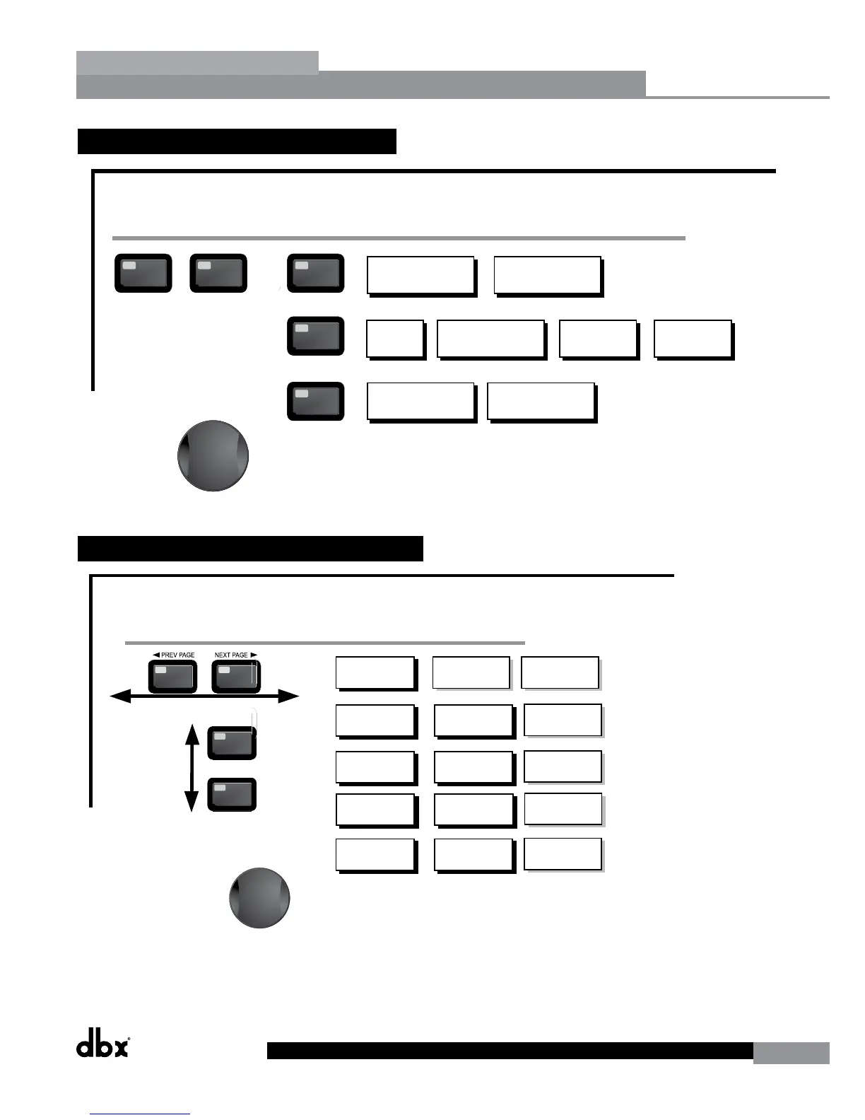
Navigating the Other Section
Subharmonic Synthesier
OTHER
OTHER
From program mode, press the Other button. Successive presses of the Other button will move you to each of the various insert modules available.
Pressing the Data Wheel will select the effect parameter to be edited.
<PREV PG NET PG
Successive presses of the Data wheel will select
effect parameters within the currently selected page.
Successive presses of the Data wheel will select
effect parameters within the currently selected page.
The NET and PREV
buttons scroll through
the pages of selected module.
Navigating the WIZARD Section
RTA/WARD
SYSTEM SETUP
AUTO E WARD
AFS WARD
GE Setup-Dual Mono
or Stereo Lined
Main Speaer Select-
See list
Sub Speaer Select-
See list
Amp Select-
High, Mid, Low
See list
Amp Sensitivity-
High, Mid, Low
Amp Level
High, Mid, Low
Low Amp
ridged/
Normal-
Load New
Program-
nsert 1 Setup-
Select
nsert 2 Setup-
Select
Noise gate-
AGC-
Limiter Limiter -6
Connect Mic Pin Noise Level
-nf to 20d
Auto E - L Auto E - R Auto E - L-R
Left and Right when using
Lined Graphic E
Select Number of
Fixed Filters
- 0-12
Mixer gain turn
down prompt
Select Type -
Low, Med, High mode
Mixer Gain Adust-
WARD
From program mode, press the RTA/WARD button. Pressing the Data Wheel will select the effect parameter to be edited.
<PREV PG NET PG
Fixed Filter Setup
Done-
Successive presses of the Data wheel will select
effect parameters within the currently selected page.
Navigating the Utility/Meters Section
LCD Contrast 1-16
AE Plot - RTA/GE
UTLTY
PUP Prog. - Current/Stored
PUP Mute - Current/Stored
C Panel - 1-6
Store - Edit Panel
Security Level - Module Select
Security Level- Low, Med, High
260 Device Level-
Low, Med, High
Edit High Password
Edit Medium Password
Program List Sie- 1-10
List ndex - 1-10
Program Change mode
Normal/Program
Program Number Loc 1-2
Output umpers - 1-6
Setting - 1, 22, 0d
UTLTY
METERS
From program mode, press the UTLTY button. Pressing the Data Wheel will select the effect parameter to be edited.
Pressing and holding the Utility button will enter you into the meter mennu
Navigating the Subharmonic Synthesizer Section
Subharmonic - -On/Off
Subharmonics 0-100
2-6H Level - 2-6H
6-6H Level - 6-6H
Subharmonic
SUHARMONC
From program mode, press the SUHARMONC button. Pressing the Data Wheel will select the effect parameter to be edited.
Successive presses of the Data wheel will select
effect parameters within the currently selected page.
Advanced Feedbac Suppression AFS
OTHER
Notch- On - Off
Flatten/Restore
Notch Filter
OTHER
Fre 1-6 1.H-20.2H
Gain- -6d - 6d
- 16,2,6,12
Subharmonic - -On/Off
Subharmonics 0-100
2-6H Level - 2-6H
6-6H Level - 6-6H
1-
one Controller-
1-
Output Tr ims
1-
Output Tr ims
-6
one Controller-
-6
2.6 Navigating the Dynamics Section
Navigating the Dynamics Section
The Comp/Limiter button
toggles through the AGC
Compressor or
Limiter modules used in
each channel of
the selected
program.
COMP
Comp On/Off
Auto On/Off
Over Easy Off, 1-10
DYNAMICS
Threshold -40 to-20dB
Ratio
1:1 to Inf:1
Gain
-20 to 20dB
Attack 0.1 to 200ms
Hold
30 to 200ms
Release
360 to 5.0dB/s
Max Atten o to Inf
GATE
Gate On/Off
Ratio
1:1 to Inf:1
Threshold -50-22dB
Attack 0.1 to 200ms
Hold
30 to 200ms
Release
360 to 5.0dB/s
Attack .20 to 5 sec
Release
30 to 1.0dB/s
AGC(Pre)
AGC On/Off
Target
-20-20dBu
Gain 1 to 20dB
Window 1 to 10dB
Hold
30 to 200ms
Low Thresh -60to-30dB
Attack .20 to 5 sec
Release
30 to 1.0dB/s
AGC(Post)
AGC On/Off
Target
-20-20dBu
Gain 1 to 20dB
Window 1 to 10dB
Hold
30 to 200ms
Low Thresh -60to-30dB
DYNAMICS
From program mode, press the comp/limiter button to move to eithter the Dynamics module. Once you have reached the Dynamics module,
successive presses of Dynamics button will move through each channel that utilizes either a Compressor (pre Crossover) or Limiter (post-crossover) module.
Navigate through the Pages of the selected compressor or Limiter module by pressing the "Next Page" or "Prev Page" buttons successively until you arrive at the desired Page.
Attack 0.1 to 200ms
Hold
30 to 200ms
Release
360 to 5.0dB/s
LIMITER
Limiter On/Off
Over Easy Off, 1-10
Threshold -40-20dB
PeakStop On/Off
Auto On/Off
Overshoot 2 to 6dB
Successive presses of the Data wheel will select
effect parameters within the currently selected page.