52
DriveRack
®
DriveRack® 260 User Manual
Remote Control
Section 6
ZONE CONTROLLER WIRING
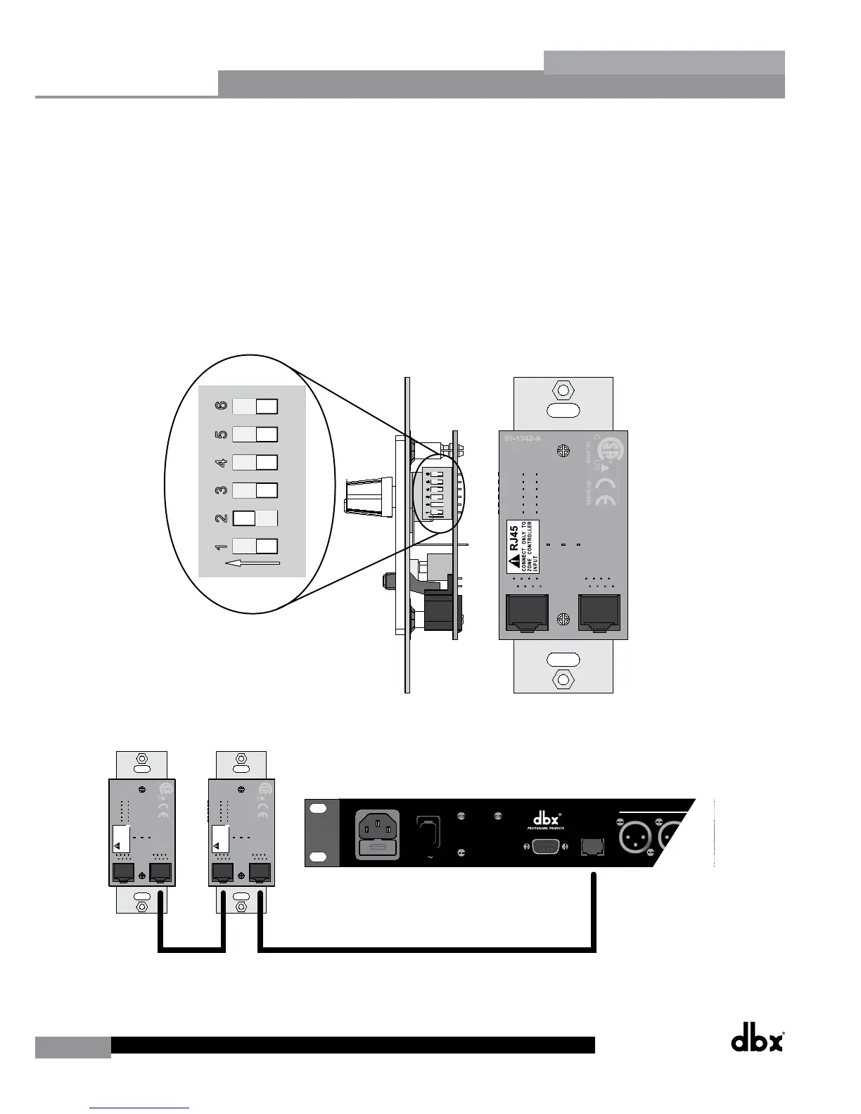
The DriveRack 260 Zone Controllers, (ZC-1, ZC-2, ZC-3, ZC-4) can be wired serially or in parallel. To wire in series each
Zone Controller must have an identification or zone number chosen using the DIP switches on the side of the controller
(see diagram A). Each controller must have a unique number chosen, although there may be multiple Zone Controllers
controlling a single zone, or a single Zone Controller that controls multiple outputs. The Zone Controllers can then be
wired together and connected to the DriveRack 260 (see diagram B).
The Zone Controllers may also be wired in parallel with the use of the ZC-BOB. To wire in parallel (home run cabling),
each controller must have a unique identification or number chosen using the DIP switches on the rear of the panel (see
diagram A). It is good practice to match the ID # of each ZC with the corresponding numbered port on the ZC-BOB. To
wire in parallel, each controller must be wired into a port of the ZC-BOB with a connecting wire going to the DriveRack
260 (see diagram C).
Diagram A
RJ45
CONNECT ONLY TO
ZONE CONTROLLER
INPUT
.
IEC6006 5
UL-650 0
80-1342- A
RJ45
CONNECT ONLY TO
ZONE CONTROLLE
R
INPUT
.
IEC6006 5
UL-650 0
80-1342- A
18 WA TTS
100V -120V 50/60H z
CH 6
CH 5PC
POWER
A HARMAN INTERNA TIONAL
COMP ANY SAL T LAKE CITY ,UTA H
MADE IN USA
MODEL DriveRack 260
COMPLETE E Q&LOUDSPEAKER
MANAGEMENT SYSTEM
TM
ZON ECONTROLLER
Use onlywitha250V fuse
Employer uniquement avao
un fusible de 250V
ID#1 ID#4
Diagram B