55xGenComm1_29
51
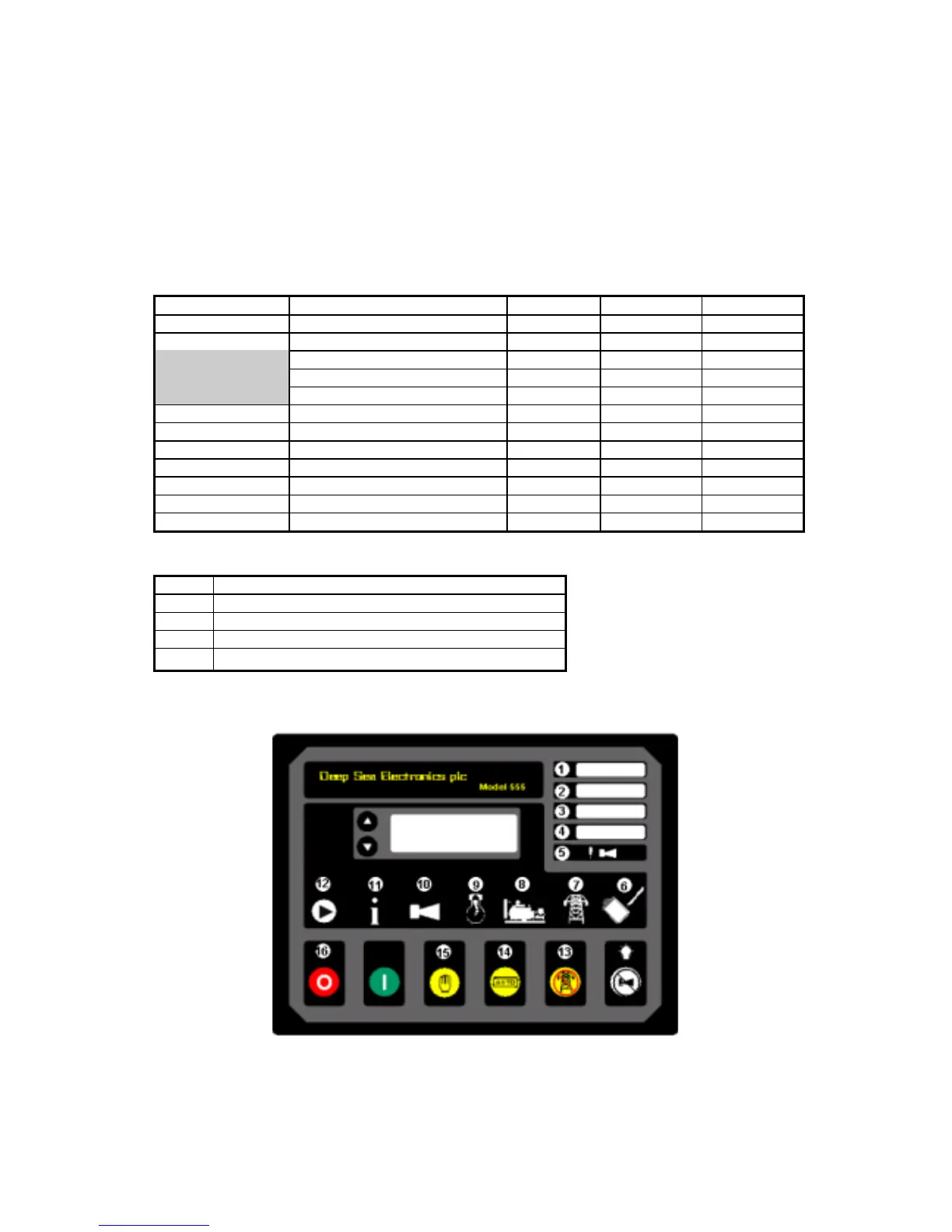
GenComm Page 14 - Diagnostic - LEDs
1. These registers represent the state of the actual LEDs on the control unit and can be used for
creating module mimics or diagnostic displays.
2. Register 0 indicates the number of LEDs that are supported. The 55x module support only up
to LED 16. 52xx module supports upto LED 30.
3. Attempting to read past register 4 from a 550 / 555 module will return 15 (unimplemented).
Registers
These are all read only registers
Register offset Name Min value Max value Bits/ Sign
0 Number of LEDs 0 128 16
1 LED 1 0 15 13/16-16/16
LED 2 0 15 9/16-12/16
LED 3 0 15 5/16-8/16
LED 4 0 15 1/16-4/16
2 LEDs 5-8 0 15 16
3 LEDs 9-12 0 15 16
4 LEDs 13-16 0 15 16
5 LEDs 17-20 0 15 16
6 LEDs 21-24 0 15 16
7 LEDs 25-28 0 15 16
8 LEDs 29-32 0 15 16
LED codes
Code Colour
0 Not lit
1 Reserved
2 Lit (All LEDs are red on 550 / 555 control modules)
15 Unimplemented LED
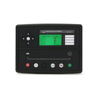
LED identification (55x)