MAINTENANCE NOTICE
NM-275 index 09 Page 2/50 September 2021
TABLE OF CONTENTS
1 MANAGEMENT OF EVOLUTIONS 4
2 SAFETY 5
2.1 Important information 5
2.2 General informations 5
3 INTRODUCTION 6
4 ASSEMBLY 7
4.1 Disassembling the unit 7
4.1.1 Disassembing the actuator unit 7
4.1.2 Disassembling the components of the unit 8
4.2 Reassembling the signaling unit 9
4.2.1 Reassembling the solenoid valves 9
4.2.2 Reassembling the module 9
4.2.3 Reassembling the unit on the actuator 10
5 ELECTRICAL CONNECTION 11
5.1 Digital / IO Link modules 11
5.1.1 Digital / IO-Link 1EV module (Ref. 7162001) 11
5.1.2 Digital / IO-Link ,2EV or 3EV module (Ref. 7162002) 12
5.2 AS-I modules 13
5.2.1 AS-i 1EV module (Ref. 7162003) 13
5.2.2 AS-i 2EV or 3EV module (Ref. 7162004) 14
6 AS-i MODULE VERSIONS 15
6.1 Wiring to the AS-i network 15
6.2 The AS-i network 16
6.2.1 AS-i power supplies 16
6.2.2 AS-i address programming 16
6.3 Technical specifications of the AS-i LED modules 17
7 PNEUMATIC CONNECTION 18
7.1 1EV Sorio
®
unit 18
7.1.1 On DP(A)X, DCX3/4 and NEOS actuators 18
7.2 Sorio
®
Double acting unit 19
7.2.1 On DP(A)X, DCX3/4 and NEOS actuators 19
7.3 2EV Sorio
®
unit 20
7.3.1 On VEOX actuator 20
7.3.2 On VDCI MC actuator 20
7.4 3EV Sorio
®
unit 21
7.4.1 On VEOX actuator 21
7.4.2 On VDCI MC actuator 21
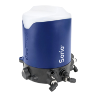
8 USE OF THE Sorio
®
UNIT 22
8.1 Main Menu 22
8.2 Automatic calibration 23
8.3 Manual calibration 24
8.4 Changing LED colours 26
8.4.1 Changing RGB LED colour valve open / valve closed: 26
8.4.2 Color change RGB LED upper valve & lower valve pulse (version 3EV) 28
8.5 Changing tolerances 30
8.6 Pigging mode 32