01.01.2022 ASSEMBLY AND OPERATING MANUAL DEGER D25H, D60H, D80 and D100 Page 19
6.1 Assembling the base frame
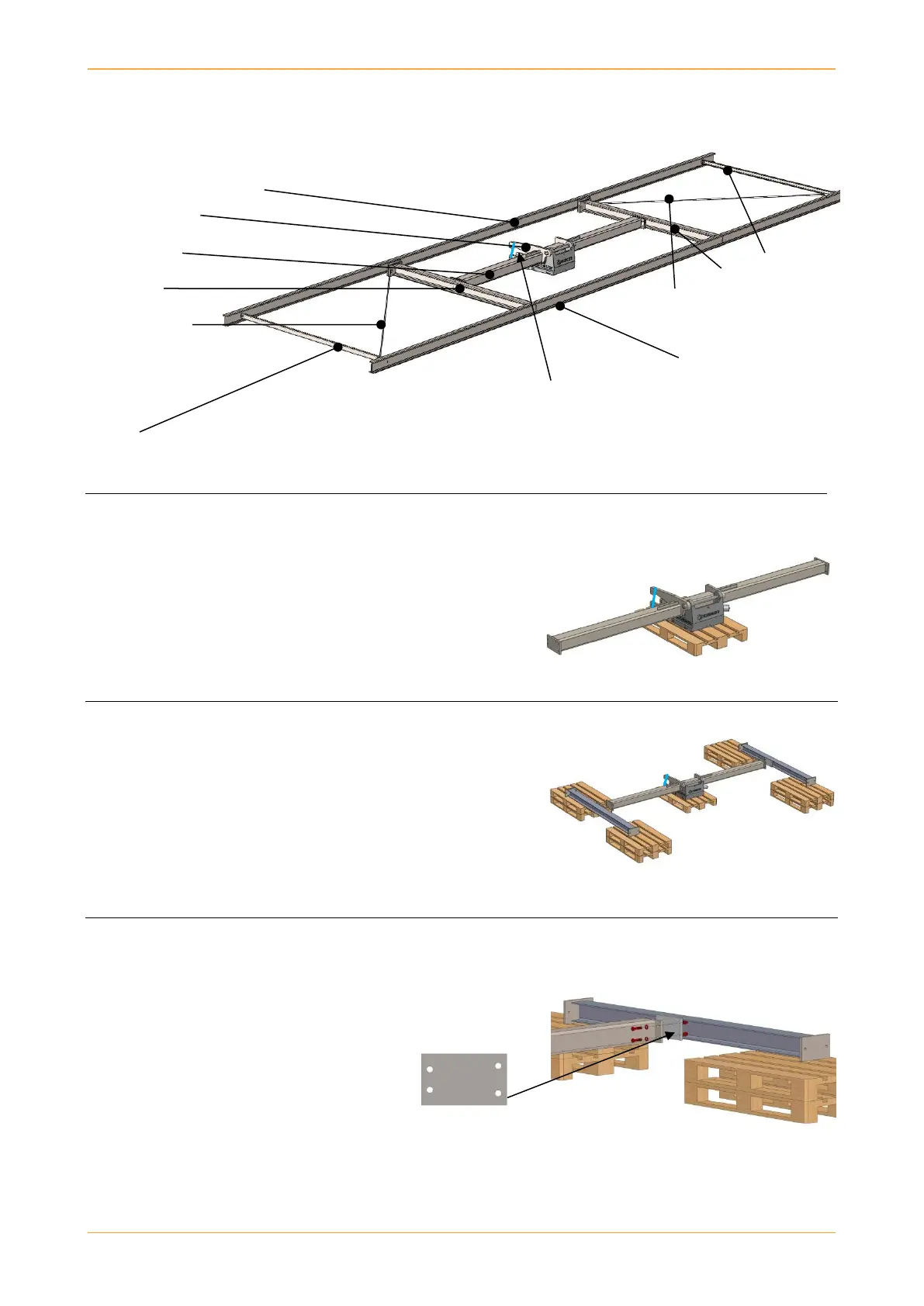
Upper longitudinal beam
Toggle lever
Central tube U-section
Cross-bar
Cross-bar
Tension rope (only
Tension rope DEGER systems D100)
(only DEGER systems
D100) Lower longitudinal
beam
Ratchet strap on toggle lever
(must not yet be removed!)
U-section
1. The pallet under the rotating head must not be removed,
otherwise there is a danger of damaging the AZ-drive. Place
the rotating head with the pallet on level ground.
2. Place appropriate support structure under the corner
points of the cross-bars, as seen in exemplary picture right.
The structure should be levelled to a uniform level of +/-
1 cm.
3. Fasten both cross-bars with four bolts M16x70, washers
and self-locking nuts M16 each to the flange of the central
tube.
Due to the asymmetric arrangement of
holes, the cross-bars cannot be incorrectly
mounted to the central tube.
Tightening torque: 300 Nm