DESIGNER’S HANDBOOK 4189350049C EN Page 146 of 206
11.8.1.2 Analogue input with multi-point linearisation
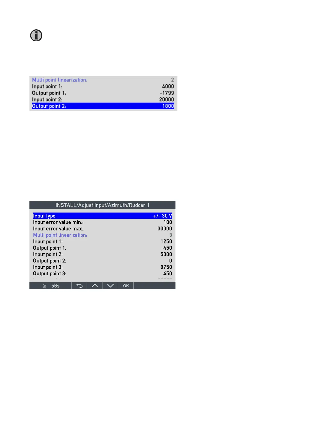
The azimuth angle input is only using 2 point linearisation (scaling) as shown below.
Input point 1: when input type is +/-20 mA, this parameter is the input current in µA that must be equal to the
Output point 1: in this case, the angle -1799 at the standard resolution of x0.1°.
Input point 2: is the input current in µA equal to the
Output point 2: in this case, the angle 1800 at the standard resolution of x0.1°.
(See also AX1 chapter)
Analogue rudder input voltage
When the analogue input is used for rudder applications, 3-point linearisation of the analogue input is normally
used. Below is a 0-10V input signal from the rudder sensor calibrated in the actual system.
In XDi it is possible to make customised VS profiles with analogue input that has up to 7-point linearisation
(see description in the AX1 chapter).
As it can be seen in the screen picture:
This VS profile use 3 point calibration.
Input point 1 is 1250mV (1.25V), that is
equal to
Output point 1: max PS rudder -450 (-45.0°)
In/out 2: 5000mV (5.0V) is the centre 0° and
In/out 3: 8750mV (8.75V) is the max SB
rudder 450 (+45.0°).

 Loading...
