EasyManuals Logo

Deif XDi Series User Manual

Deif XDi Series
206 pages
To Next Page IconTo Next Page
To Previous Page IconTo Previous Page
Page #204 background imageLoading...
Page #204 background image
DESIGNER’S HANDBOOK 4189350049C EN Page 204 of 206
In DEIF standard libraries, voltage input 3 on the AX1 module in slot 1 is always reserved for analogue dimmer and
is not used as input for any of the virtual indicators.
13.7.1 XDi-net, CAN TPDO or analogue dimmer using AX1
Dimmer
control
type
XDi-net
All controlled from
central dimmer
(AX1 not needed)
Analogue
control of XDi units on
bridge, fixed dimmer
level in ECR
TPDO
Bridge controlled from
central dimmer
ECR is local analogue
XDi device
Dimmer
input
Select PP
Dimmer
input
Select PP
Dimmer
input
Select PP
XDi 1
XDi-net
PP01
Fixed
PP06
Voltage **
PP05
XDi 2
XDi-net
PP01
Voltage *
PP02
TPDO
PP03
XDi 3
XDi-net
PP01
XDi-net
PP01
TPDO
PP03
*) The input is default set up to use a potentiometer connected to the Vref output on
AX1 module terminal 3, but it can easily be reconfigured to a dimmer voltage input instead.
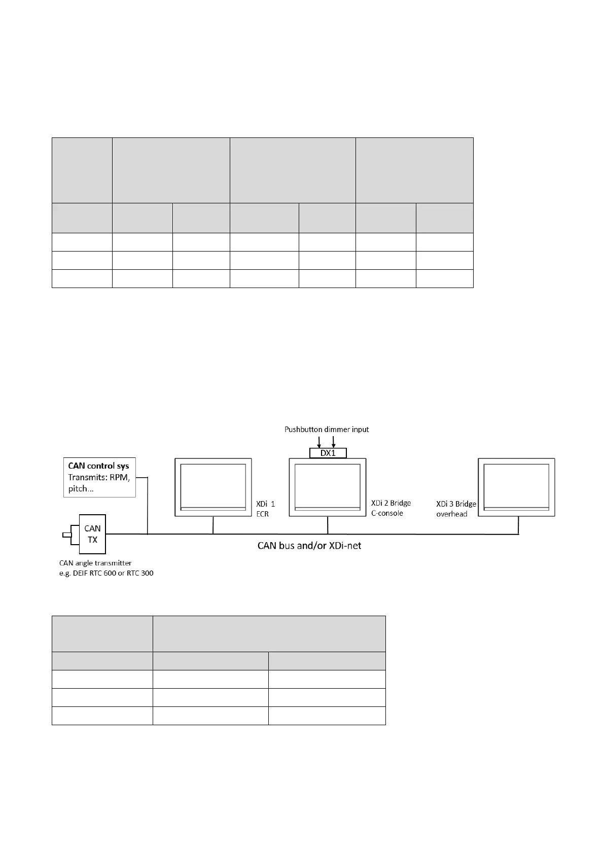
The analogue dimmer value is shared on CAN for the actual dimmer group, and since the XDi 3 is part of group 1
(default), its dimmer level will be controlled from the XDi 2 via the XDi-net.
**) This will require an AX1 module mounted on the XDi 1 located in the ECR.
13.7.2 Push-button dimmer using DX1
Dimmer control
type
Push-button control of XDi units on bridge
Fixed dimmer level in ECR
XDi device
Dimmer input
Select PP
XDi 1
Fixed
PP06
XDi 2
Digital input 1&2
PP04
XDi 3
XDi-net
PP01

Table of Contents

Questions and Answers:

Question and Answer IconNeed help?

Do you have a question about the Deif XDi Series and is the answer not in the manual?

Deif XDi Series Specifications

General IconGeneral
BrandDeif
ModelXDi Series
CategoryMeasuring Instruments
LanguageEnglish

Related product manuals