DESIGNER’S HANDBOOK 4189350049C EN Page 148 of 206
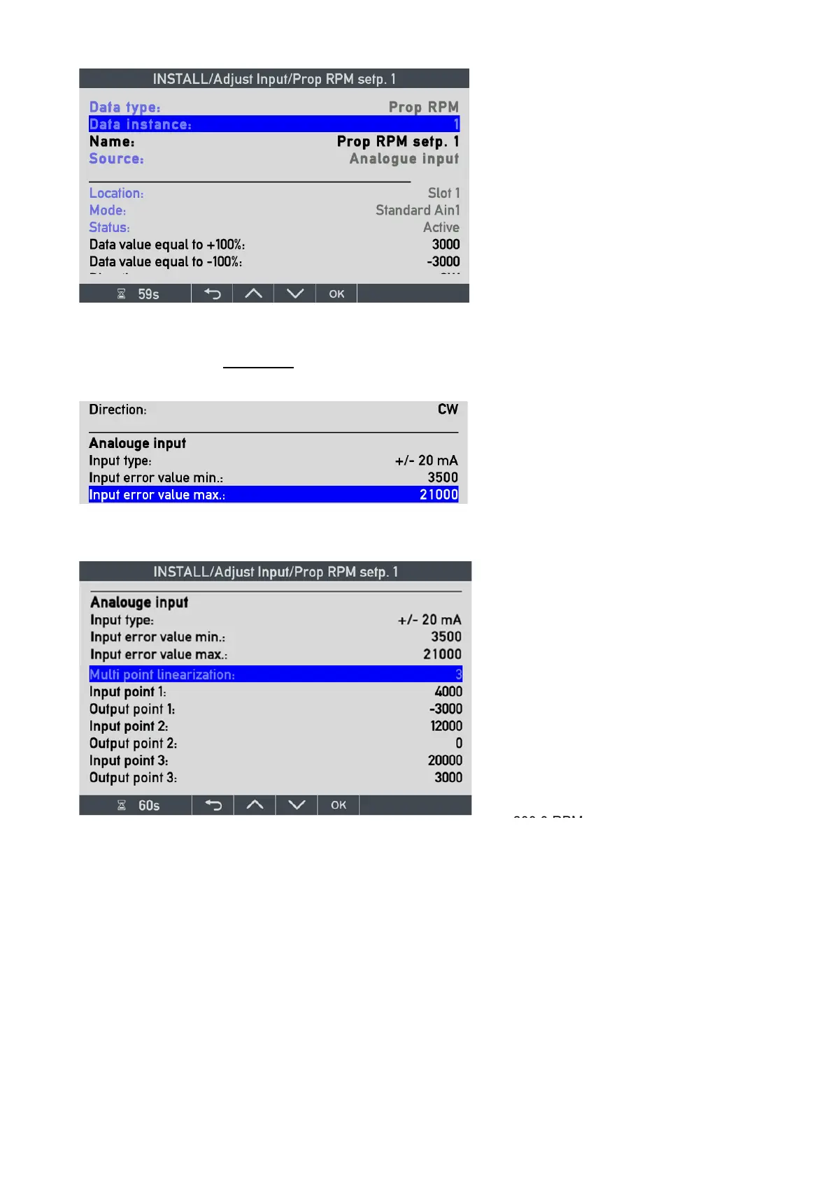
Direction: CW/CCW can also be set up to change the conversion direction of the analogue input, but please note
that it is the sign of the input signal the CW/CCW function is changing, so it is not of any use in a 4-20mA system.
Input error value min/max: See the description for azimuth / rudder
Name: identifies the input parameter, and
it may be changed.
Source: analogue input (single). This is
fixed defined in the selected VS.
Data value equal to +100 %: is used to
calculate the %RPM set point value (and
also %Thrust (%RPM)
2
and %Power
(%RPM)
3
. If those data are used by the
indicator and set up in the VS).
Input type: can be changed. See
previous description of AX1 for azimuth.
Multi-point linearisation:
RPM is +/- type; therefore 3-point
linearisation is used.
Input point 1: 4000 µA (4 mA) equals the
output point 2: -3000 res. x0.1 that is
equal to -300.0 RPM.
Input point 2: 12000 µA is 0 RPM
Input point 3: 20000 µA is set to output
300.0 RPM.

 Loading...
