DESIGNER’S HANDBOOK 4189350049C EN Page 61 of 206
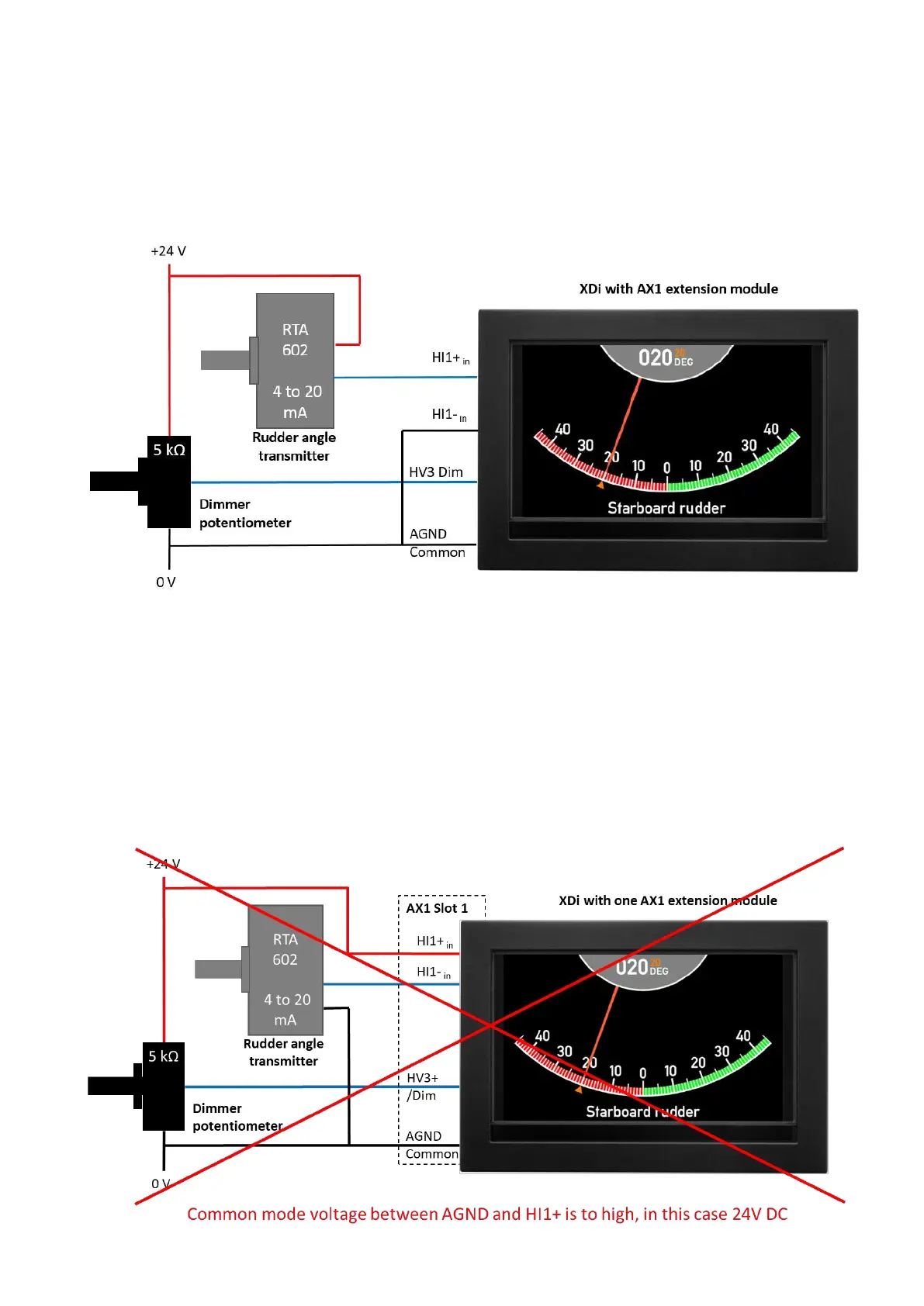
5.6.7.1 Example: rudder angle indicator system correctly configured (current source)
The RAI system is with a DEIF RTA 602 rudder angle transmitter 4 to 20 mA, and with an external dimmer, all is
supplied from the same 24 V DC source. When connecting the RTA to +24 V DC and the XDi 4 to 20 mA current
input HI1- to AGND (common), the common mode voltage from HI1+ to AGND will in the worst case be
approximately 1.2 V and is well within the +/-15 V common mode limit.
5.6.7.2 Example of an incorrect RAI system configured (current sink) and some solutions
In this example the RTA angle transmitter is in a current sink configuration, where the RTA is connected to 0 V
(AGND), and the XDi 4 to 20 mA current input HI1+ is connected to +24 V. The common mode voltage from HI1+
to AGND (common) will be 24 V, and this exceeds the +/-15 V common mode limit, and the system will not work,
and the indicator will constantly be out of range!

 Loading...
