Installing Power Modules | 23
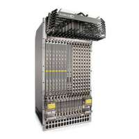
Figure 5-2. DC PEM Locations
DC Requirements
Redundancy
For full facility redundancy, install two DC PEMs where each PEM must be attached to an independent
power source with a dedicated circuit breaker sized in accordance with your local building and electrical
safety codes.
Cable and Connector Requirements
You must provide your own cables to connect to a remote power source (a circuit breaker panel, for
example) in your equipment rack or facility. Cables must be sized to meet the following criteria:
• Rated for 60A service to allow for a fully loaded E300 system per NEC in the United States or
internationally, per local safety codes.
• Limit voltage drop across the cable length to 0.5V or less.
Before you make the cable connections, apply a coat of anti-oxidant paste to unplated metal contact
surfaces. File unplated connectors, braided straps, and bus bars to a shiny finish. It is not necessary to file
and coat tinned, solder-plated, or silver-plated connectors or other plated connection surfaces, such as
those on the PEM studs.
NOTE: Please take precautions against over-tightening the screws or nuts on this device.
Maximum Power Dissipation 2400W
Maximum DC PEM Input Current 60A
Optional Grounding
Holes
fn00121cHH
ir Filter
DC Power Supply
Slot 0
DC Power Supply
Slot 1
 Loading...
