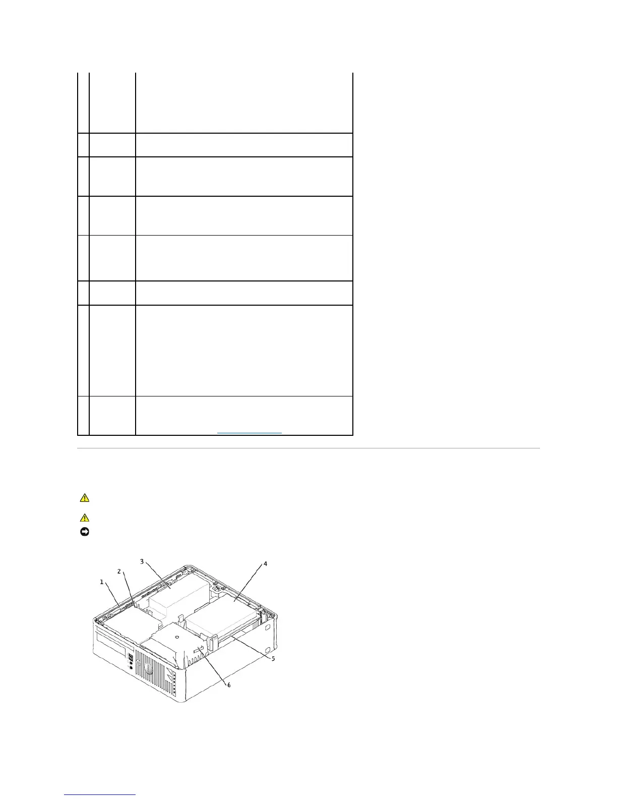
Inside Your Computer
NOTE: Do not plug a telephone cable into the network connector.
On computers with a network connector card, use the connector on the
card.
It is recommended that you use Category 5 wiring and connectors for
your network. If you must use Category 3 wiring, force the network
speed to 10 Mbps to ensure reliable operation.
Flashes a yellow light when the computer is transmitting or receiving
network data. A high volume of network traffic may make this light
appear to be in a steady "on" state.
Use the blue line-in connector (available on computers with integrated
sound) to attach a record/playback device such as a cassette player, CD
player, or VCR.
On computers with a sound card, use the connector on the card.
Use the green line-out connector (available on computers with
integrated sound) to attach headphones and most speakers with
integrated amplifiers.
On computers with a sound card, use the connector on the card.
Use the pink microphone connector (available on computers with
integrated sound) to attach a personal computer microphone for voice or
musical input into a sound or telephony program.
On computers with a sound card, the microphone connector is on the
card.
Use the back USB connectors for devices that typically remain connected,
such as printers and keyboards.
Plug the cable from your VGA-compatible monitor into the blue connector.
NOTE: If you purchased an optional graphics card, this connector will be
covered by a cap. Connect your monitor to the connector on the graphics
card. Do not remove the cap.
NOTE: If you are using a graphics card that supports dual monitors, use
the y-cable that came with your computer.
Connect a serial device, such as a handheld device, to the serial port.
The default designations are COM1 for serial connector 1 and COM2 for
serial connector 2.
For more information, see "System Setup Options."
CAUTION: Before you begin any of the procedures in this section, follow the safety instructions in the Product Information Guide.
CAUTION: To avoid electrical shock, always unplug your computer from the electrical outlet before removing the computer cover.
NOTICE: Be careful when opening the computer cover to ensure that you do not accidentally disconnect cables from the system board.