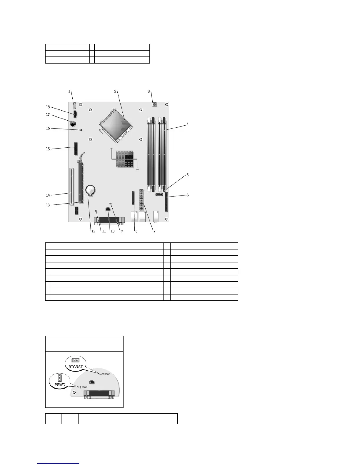
System Board Components
Jumper Settings
The jumper locations are shown below.
heat sink and blower assembly
intrusion switch connector (INTRUDER)
processor connector (CPU)
power connector (12VPOWER)
memory module connectors (DIMM_1, DIMM_2, DIMM_3, DIMM_4)
PCI Express x16 connector (SLOT1)
serial ATA drive connector (SATA0,)
front-panel connector (FNT_PANEL)
standby power indicator (AUX_PWR)
CD/DVD drive connector (IDE)
system board speaker (BEEP)
RTC reset jumper (RTCRST)
internal speaker (INT_SPKR)
Small Form Factor Computer