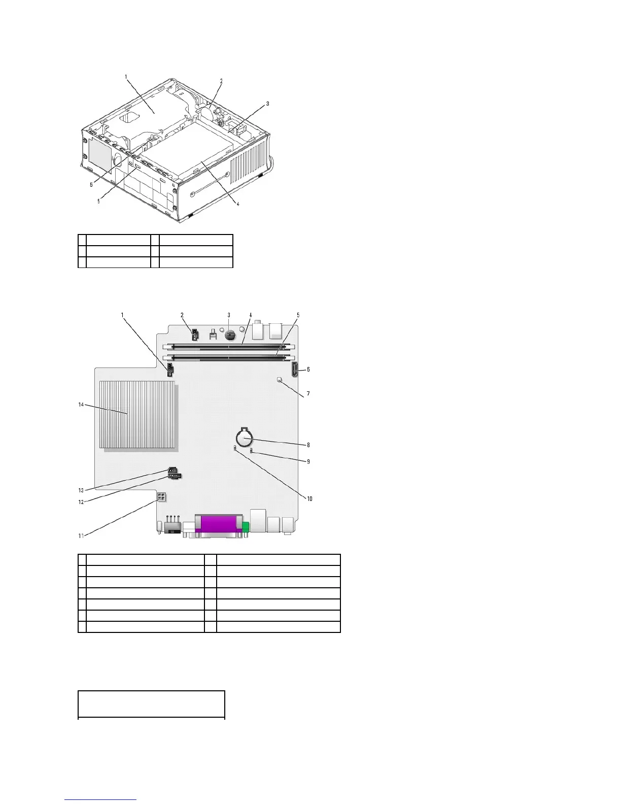
System Board Components
Jumper Settings
The jumper locations are shown below.
fan connector (FAN_FRONT)
internal speaker connector (INT_SPKR)
clear CMOS jumper (RTCRST)
system board speaker (BEEP)
channel B memory connector (DIMM_2)
hard-drive power connector (SATA_PWR)
channel A memory connector (DIMM_1)
SATA data cable connector(SATA0)
intrusion switch connector (INTRUDER)
standby power indicator (AUX_LED)
microprocessor heat-sink assembly
Ultra Small Form Factor Computer