12. Remove the keyboard.
13. Remove the primary memory.
14. Remove the heat-sink assembly.
15. Remove the inner frame.
About this task
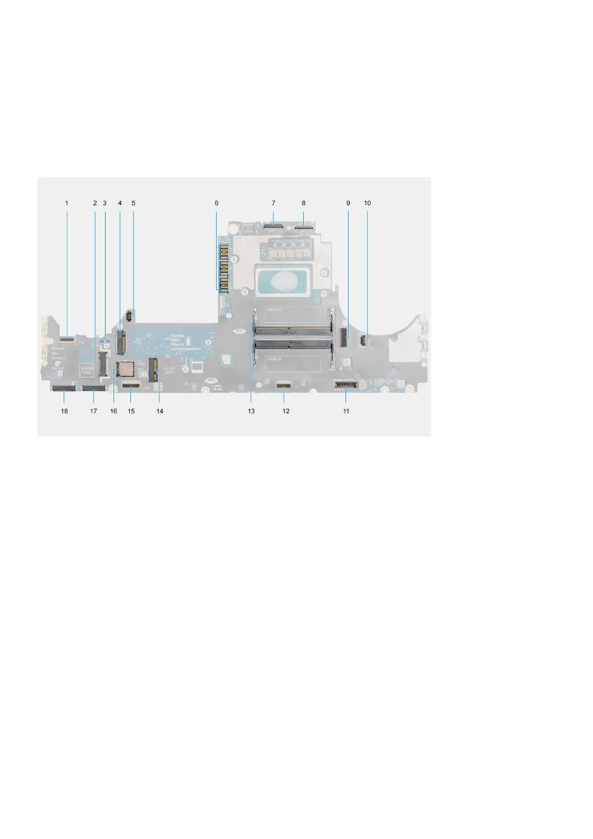
The figure indicates the location of the system board and provides a visual representation of the removal procedure.
The following image indicates the connectors on your system board:
1. Power button FFC connector
2. WWAN card connector
3. Darwin antenna cable connector
4. Secondary M.2 SSD connector
5. Fan cable connector
6. FPC beam connector
7. Display cable connector
8. IR camera/Touchscreen cable connector
9. Power-adapter port connector
10. Fan cable connector
11. Battery cable connector
12. Touchpad cable cpnnector
13. Secondary memory module slot
14. WLAN card connector
15. USH daughter board cable connector
16. SIM card slot
17. Primary M.2 SSD slot 3 connector
18. Primary M.2 SSD slot 5 connector
Removing and installing components
71