• Maximum supported DIMM frequency of the processors
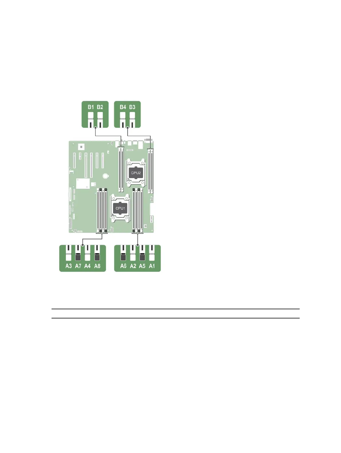
Your system contains 12 memory sockets split into four sets— two sets of 4 sockets and two sets of 2
sockets each. DIMMs in sockets A1 to A8 are assigned to processor 1 and DIMMs in sockets B1 to B4 are
assigned to processor 2. Each 4-socket set is organized into two channels and each 2–socket set is
organized into one channel. In each channel of the 4-socket set, the release levers of the first socket are
marked white and those of the second socket are marked black. In the 2-socket set, each release lever is
marked white.
Figure 53. Memory socket locations
Memory channels are organized as follows:
Table 30. Memory channels
Processor Channel 0 Channel 1 Channel 2 Channel 3
Processor 1 slots A1 and A5 slots A2 and A6 slots A3 and A7 slots A4 and A8
Processor 2 slot B1 slot B2 slot B3 slot B4
The following table shows the memory populations and operating frequencies for the supported
configurations.
128