5. Disassembly and Assembly Procedures
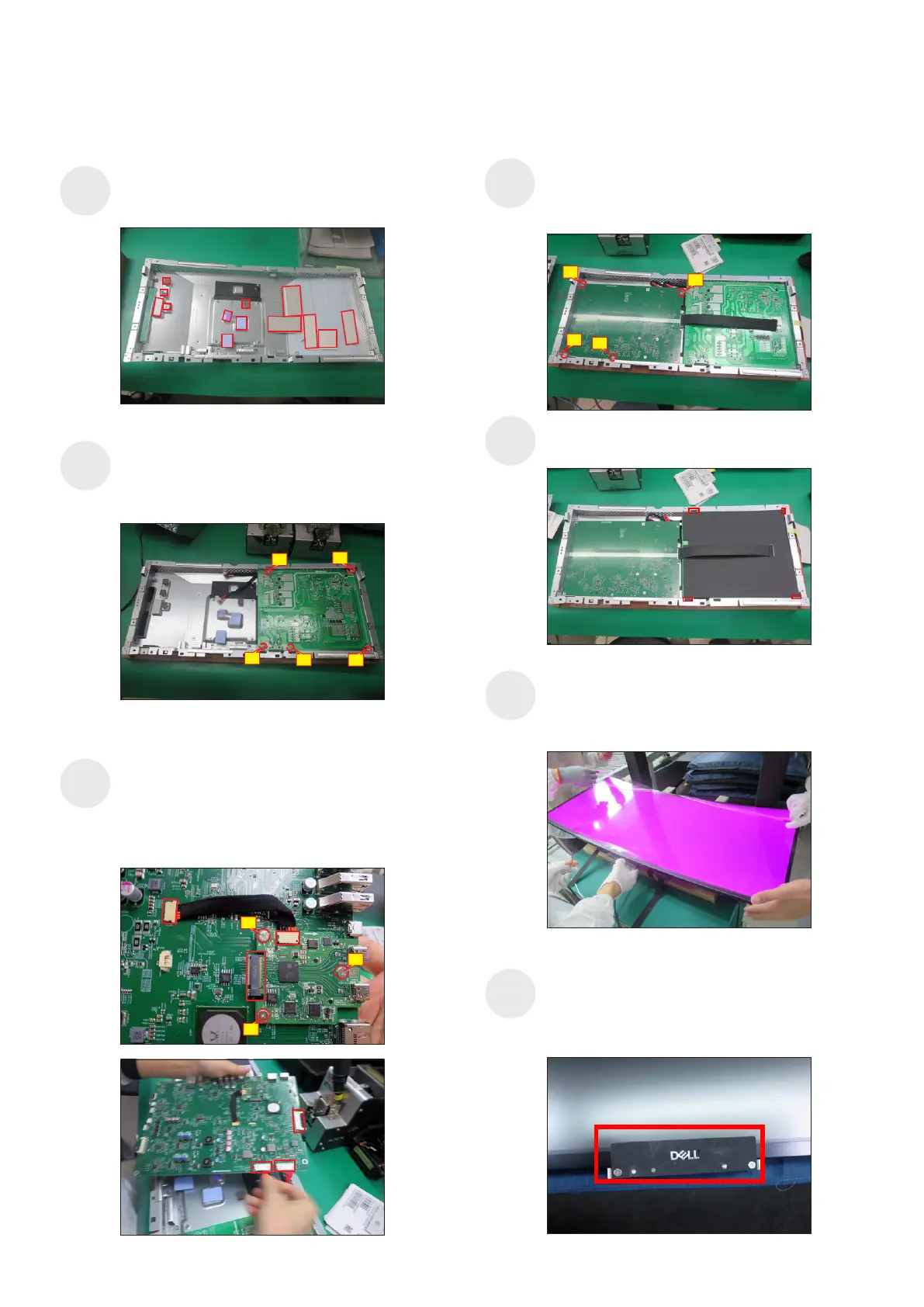
No.2~5 screw size=M3x6, Torque=5±1kgfxcm)
Put 1pcs power board into the bracket, then use a
Philips-head screwdriver to tighten 5pcs screws for
locking the power board.
(No.1 screw size=M4x8, Torque=5±1kgfxcm;
S2
Take 1pcs TBT board to insert the connector of the
interface board, then use 1pcs cable to connect the
TBT board with interface board. Use a Philips-head
screwdriver to tighten 3pcs screws for locking the
TBT board. Connect 1pcs eDP cable and two power
connective cables to the interface board.
(No.6~8 screw size=M3x6, Torque=5±1kgfxcm)
S3
2
4
3
5
Place a bracket chassis base on a protective
cushion, then stick 13pcs Silicon sheets on the
position as the picture below shown.
5.2 Assembly Procedures:
S1
S4
Panel preparation: Take out 1pcs panel module from
the carton, remove the protective film by tearing off
all the tapes of screen, then examine the panel
surface according to inspection criteria carefully.
S5
Take 1pcs Dell nameplate, then use a locating fixture
to fix the nameplate to the bezel of the module, and
then move the whole unit into a laminating fixture,
use the machine to press the nameplate with the
bezel firmly attachment.
S6
10
9
12
Turn over the interface board and locate it into the
bracket, then use a Philips-head screwdriver to
tighten 4pcs screws for locking the interface board.
(No.9~12 screw size=M3x6, Torque=5±1kgfxcm)
1
6
7
8
Take a black mylar to insert the hooks of the bracket
to cover the power board.
11
S7
 Loading...