5. Disassembly and Assembly Procedures
5.1 Disassembly Procedures:
- Screwdriver(Phillip head) #1
- Penknife
- Screwdriver(Phillip head) #2
Tool Description:
Tool Required:
- Soldering iron and absorber
List the type and size of the tools that would typically can be
used to disassemble the product to a point where components
and materials requiring selective treatment can be removed.
NOTE:
This “Disassembly and Assembly Procedures” is for EMEA only,
not for other regions. Please note that Dell will deem warranty void
if any disassembly is done on the monitors.
S2
S1
S3
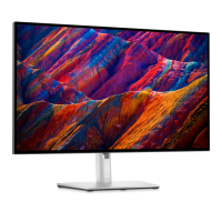
Remove the monitor stand base:
1. Place the monitor on a soft cloth or cushion.
2. Press and hold the stand-release button.
3. Lift the stand up and away from the monitor.
Wedge your fingers between the rear cover and the
middle bezel on the corners of the top side of the
monitor to release the rear cover, then use one hand
to press the middle bezel, the other hand to pull up
carefully the rear cover in order of arrow preference
for unlocking mechanisms of rear cover.
Use a Philips-head screwdriver to remove 4pcs
(No.1~4 screw size=M4x11; Torque=10±1kgfxcm)
screws for unlocking mechanisms.
2
3
4
1
5
2
1
3
4
S4
S7
S6
S5
Lift up the rear cover, and disconnect the joystick
cable and sensor cable away from the connectors,
and then remove the rear cover and put it aside.
Release the cables by tearing off all the tapes. Use a
Philips-head screwdriver to remove 2pcs screw for
unlocking the joystick board, then release the joystick
board sensor board from the hooks of the rear cover.
(No.1~2 screw size=M2x2.4, Torque=1±0.2kgfxcm)
sensor board
1
2
(No.1~2 screw size=M3x4,Torque=5±1kgfxcm)
Use a Philips-head screwdriver to remove 2pcs screws
for unlocking the IO cover with bracket, then release
the IO cover away from the main bracket chassis.
2
1
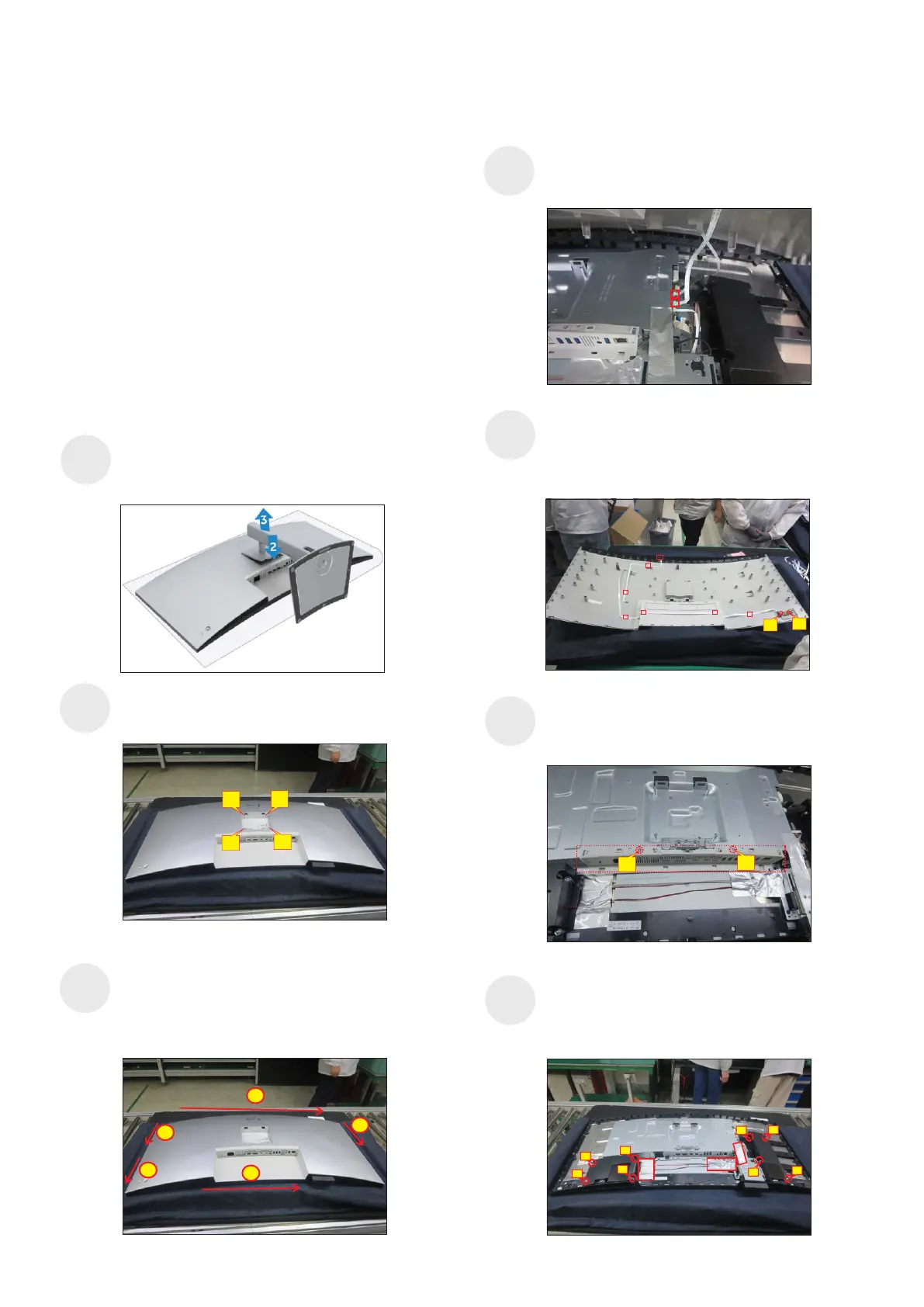
(No.1~8 screw size=M3x6, Torque=6±1kgfxcm)
Tear off 3pcs aluminum foil for releasing the cables
and bracket. Use a Philips-head screwdriver to
remove 8pcs screws for unlocking the two speakers
with middle frame.
1
3
4
2
5
8
7
6
 Loading...