5. Disassembly and Assembly Procedures
S19
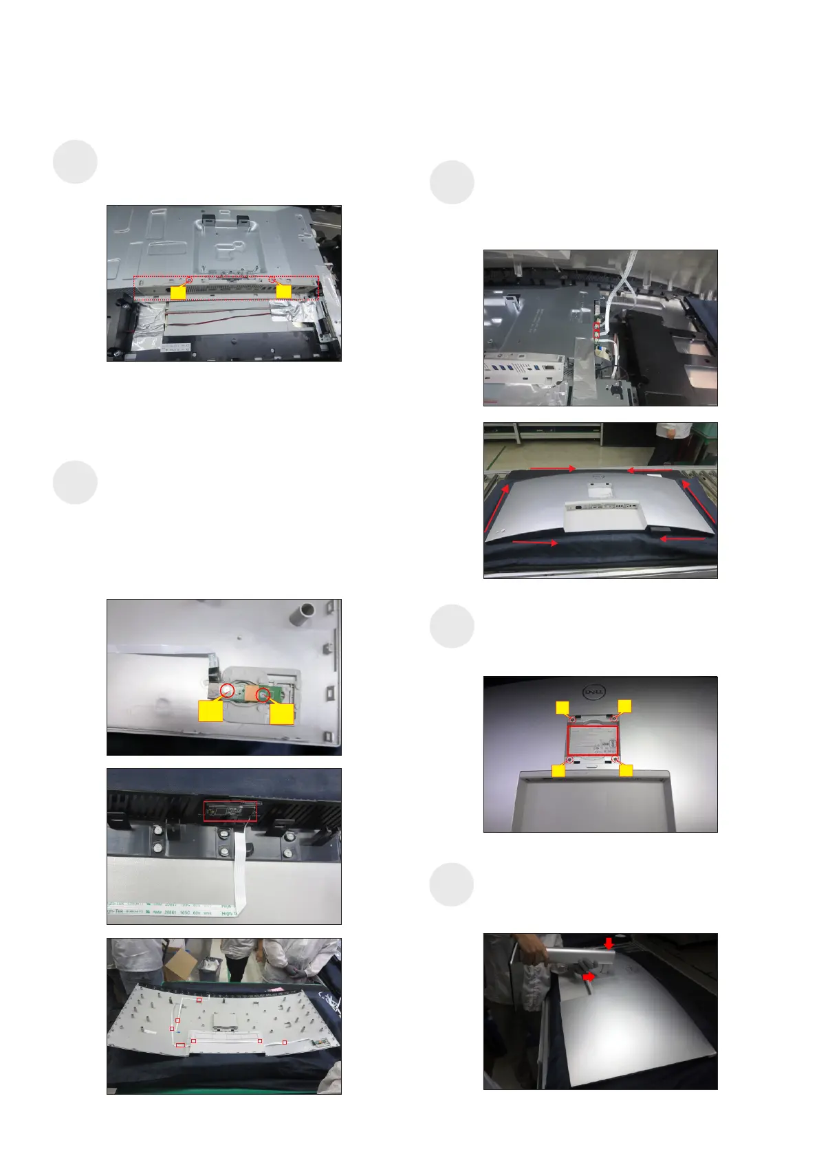
Move the assembled rear cover close to the panel
unit, then connect the joystick key cable and
sensor cable to the connectors of interface board.
Put down the rear cover and push the rear cover
on the positions marked as the picture below
shown for mechanisms engagement.
Take a stand base close to the monitor. Fit the two
tabs on the upper part of the stand into the grooves on
the back of the monitor, and then lower the stand so
that the monitor mounting area snaps onto the stand.
S21
Use a Philips-head screwdriver to tighten four
screws for locking mechanisms. Stick 1pcs label on
the specific positions as the picture below shown.
(No.1~4 screw size=M4x11; Torque=10±1kgfxcm)
S20
2
3
4
1
S18
Take 1pcs joystick key, 1pcs joystick board, 1pcs
sensor board and 1pcs rear cover, then assemble the
joystick key with the board. Locate the joystick board
to the correct position of the rear cover, then use a
Philips-head screwdriver to lock 2pcs screws for
locking the joystick board with rear cover. Locate the
sensor board to the hooks of the rear cover, then tear
off the papers on the back of the cables, and then fix
the joystick cable and sensor cable on the rear cover
with tapes.
(No.1~2 screw size=M2x2.4,Torque=1±0.2kgfxcm)
S17
(No.1~2 screw size=M3x4,Torque=5±1kgfxcm)
Take 1pcs IO cover to assemble with the main bracket
chassis, then use a Philips-head screwdriver to lock
2pcs screws for locking the IO cover with bracket.
2
1
2
1
 Loading...