Do you have a question about the Dell Vostro 3401 and is the answer not in the manual?
Guidelines to protect the computer and ensure personal safety during servicing procedures.
Steps to take before opening the computer for maintenance or repair.
Essential precautions for handling electronic components and preventing damage.
Understanding and preventing electrostatic discharge damage to sensitive components.
Information on the components and usage of an ESD field service kit for protection.
Procedures to follow after completing internal computer servicing and reassembly.
Overview of USB standards, evolution, and capabilities, including USB 3.2 Gen 1.
Explanation of HDMI 1.4 features, advantages, and applications for audio/video interfaces.
Details on how power button LEDs indicate system status with and without fingerprint readers.
Identification of internal computer components with corresponding numbers from an exploded diagram.
Procedures for removing and installing the Secure Digital (SD) card.
Steps for removing and installing the computer's base cover for access to internal components.
Precautions and procedures for disconnecting, removing, and reconnecting the lithium-ion battery.
Instructions for removing and installing the computer's memory modules (RAM).
Steps for removing and installing the Wireless Local Area Network (WLAN) card.
Procedures for removing and installing M.2 2230 and M.2 2280 Solid-State Drives (SSDs).
Instructions for removing and installing the hard drive assembly.
Steps for removing and installing the coin-cell battery.
Procedures for removing and installing the system fan.
Instructions for removing and installing the heat sink assembly.
Steps for removing and installing the internal computer speakers.
Procedures for removing and installing the Input/Output (IO) board.
Instructions for removing and installing the touchpad assembly.
Steps for removing and installing the entire display assembly.
Procedures for removing and installing the display bezel.
Instructions for removing and installing the camera module.
Steps for removing and installing the display panel.
Procedures for removing and installing the display back-cover and antenna assembly.
Instructions for removing and installing the power button.
Procedures for removing and installing the system board.
Steps for removing and installing the power adapter port.
Procedures for removing and installing the palm-rest and keyboard assembly.
How to run hardware diagnostics using the Enhanced Pre-Boot System Assessment tool.
Interpretation of system diagnostic lights (LEDs) for power and battery status.
Steps to perform a WiFi power cycle to resolve connectivity issues.
Information on how to contact Dell for sales, technical support, or customer service.
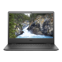
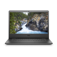
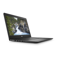
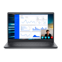
| Display | 14-inch HD (1366 x 768) |
|---|---|
| RAM | Up to 16GB DDR4 |
| Storage | Up to 1TB HDD or 512GB SSD |
| Graphics | Intel UHD Graphics |
| Operating System | Windows 10 Pro |
| Battery | 3-Cell Battery, 42WHr (Integrated) |
| Weight | 1.64 kg (3.62 lb) |
| Ports | 2 x USB 3.2 Gen 1, 1 USB 2.0, 1 HDMI 1.4, 1 SD Card Reader, 1 RJ-45 |
| Wireless | 802.11ac Wi-Fi and Bluetooth |
| Dimensions | 328.7 x 239.5 x 19.9 mm |