Chapter 4 Display and Operation|ASDA-A&A+ Series
Revision April 2009 4-11
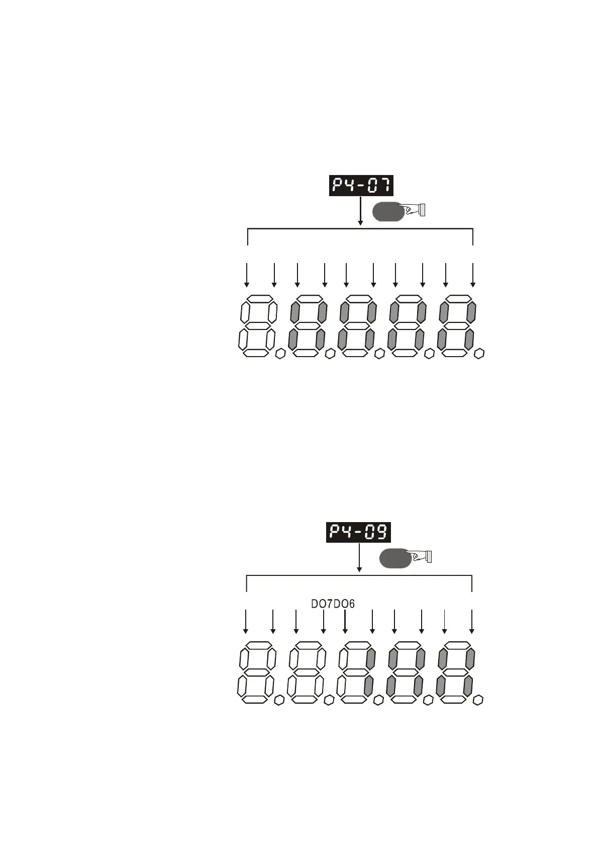
4.4.5 DI Diagnosis Operation
Following the setting method in Figure 4.7 can perform DI diagnosis operation (parameter P4-07, Input
Status or Force Input Control). According to the ON and OFF status of the digital inputs DI1 to DI8, the
corresponding status will display on the servo drive LED display. When the segment lit and display on
the screen, it means that the corresponding digital input signal is ON. (Please also refer to Figure 4.7)
Figure 4.7
ON
DI10 DI9 DI8 DI7 DI6 DI5 DI4 DI3 DI2 DI1
ONONONONONONON
OFFOFF
SET
Light:
4.4.6 DO Diagnosis Operation
Following the setting method in Figure 4.8 can perform DO diagnosis operation (parameter P4-09,
Output Status Display). According to the ON and OFF status of the digital outputs DO1 to DO5, the
corresponding status will display on the servo drive LED display. When the segment lit and display on
the screen, it means that the corresponding digital input signal is ON. (Please also refer to Figure 4.8)
Figure 4.8
ON
DO10 DO9DO8 DO5DO4 DO3DO2 DO1
ONONONON
OFFOFF OFF OFF OF F
SET
Light:
Call 1(800)985-6929 for Sales
Call 1(800)985-6929 for Sales