Chapter 6 Control Modes of Operation|ASDA-A&A+ Series
Revision April 2009 6-9
Total acceleration time = TACC + TSL
Total deceleration time = TDEC + TSL
NOTE
1) If the control of the servo motor is achieved via internal parameters, the command curve
should be defined by the users. Therefore, when the command source is internal parameter,
ensure that the setting value of P1-36 is not set to 0 or the servo motor will not accelerate or
decelerate during operation.
2) So if users change the control mode to Pr mode and switching power off and on, the servo
drive of parameter P1-36 will auto set the value to 20.
6.2.5 Electronic Gear Ratio
Relevant parameters:
P1 - 44▲
GR1 Electronic Gear Ratio (1st Numerator) (N1) Communication Addr.: 012CH
Default: 1 Related Section:
Applicable Control Mode: Pt, Pr Section 6.2.5
Unit: pulse
Range: 1 ~ 32767
Settings:
Multiple-step electronic gear numerator setting. Please refer to P2-60~P2-62.
P1 - 45▲
GR2 Electronic Gear Ratio (Denominator) Communication Addr.: 012DH
Default: 1 Related Section:
Applicable Control Mode: Pt, Pr Section 6.2.5
Unit: pulse
Range: 1 ~ 32767
Settings:
Electronic gear denominator setting.
Please set electronic gear ratio when the servo drive is Off. As the wrong setting may cause
motor to run chaotically (out of control) and it may lead to personnel injury, therefore, ensure to
observe the following rule when setting P1-44, P1-45.
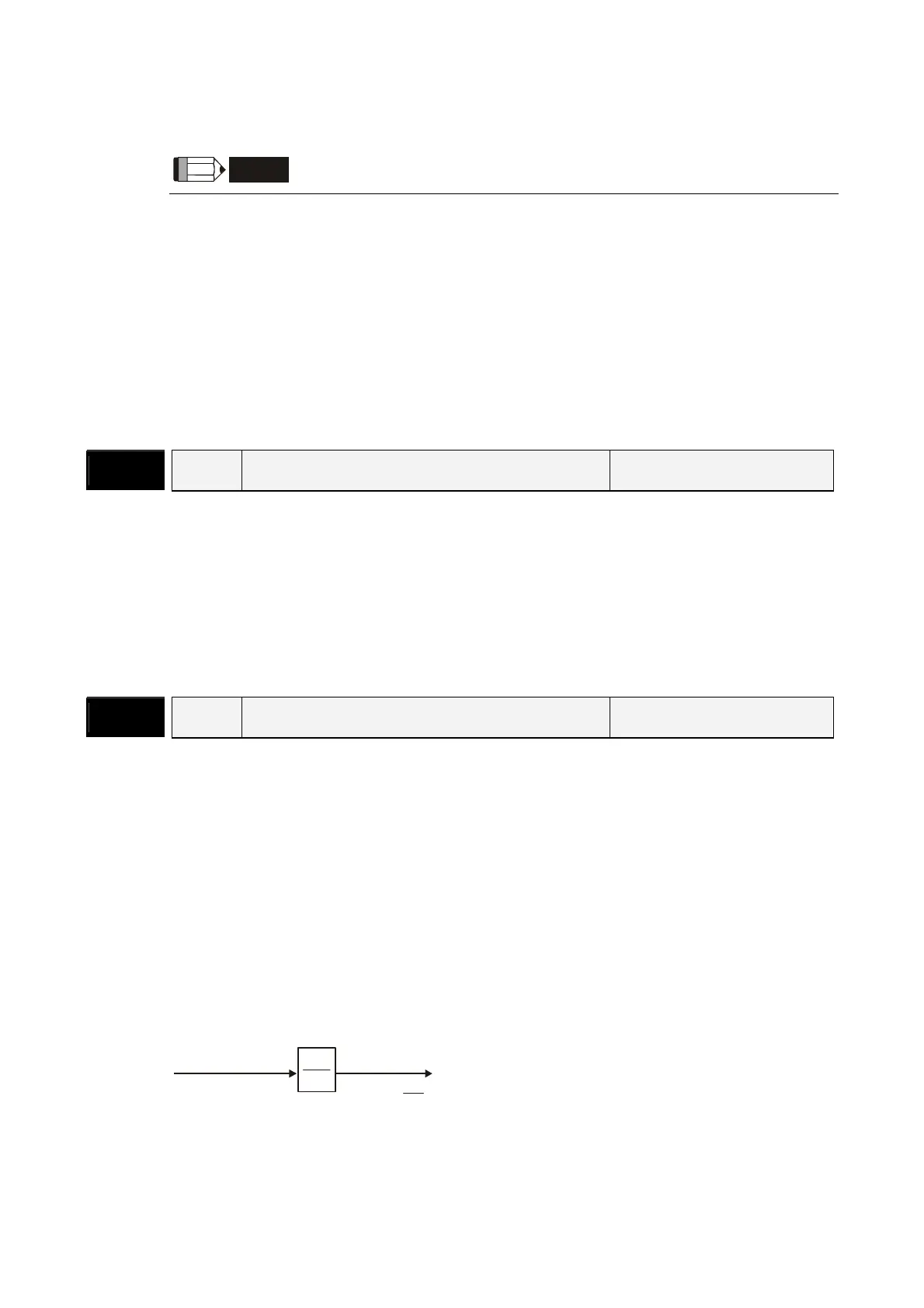
The electronic gear ratio setting (Please also see P1-44, P2-60 ~ P2-62):
f1
f2 = f1 x
N
M
N
M
Pulse input
Position
command
The electronic gear ratio setting range must be within: 1/50<N/M<200.
f1: Pulse input f2: Position command
N: Numerator 1, 2, 3, 4, the setting value of P1-44 or
P2-60 ~ P2-63
M: Denominator, the setting value of P1-45
Call 1(800)985-6929 for Sales
Call 1(800)985-6929 for Sales