Modbus TCP Remote I/O Communication Module RTU-EN01
DVP-PLC Operation Manual
6
2.4 RUN/STOP Switch
Status Explanation
1. RUN indicator on RTU-EN01 is ON.
2. Analog input/output module is in RUN status.
RUN
3. Smart PLC function is running.
1. Analog input/output module switches from RUN to STOP status.
RUN Æ STOP
2. Y points on digital input/output module are all OFF.
1. RUN indicator on RTU-EN01 is OFF.
2. Analog input/output module is in STOP status.
STOP
3. Smart PLC function stops.
1. RTU-EN01 re-detects the information on the right-side module.
STOP
RUN
STOP Æ RUN
2. Analog input/output module switches from STOP to RUN status.
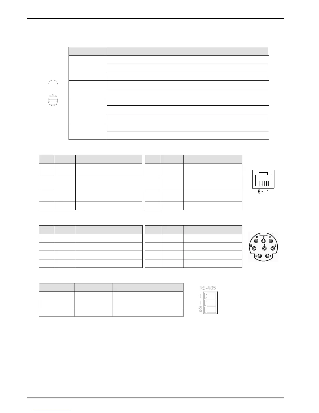
2.5 RJ-45 PIN Definition
PIN Signal Definition PIN Signal Definition
1 Tx+
Positive pole for data
transmission
5 -- N/C
2 Tx-
Negative pole for data
transmission
6 Rx-
Negative pole for data
receiving
3 Rx+
Positive pole for data
receiving
7 -- N/C
4 -- N/C 8 -- N/C
2.6 RS-232 PIN Definition
PIN Signal Definition PIN Signal Definition
1 -- N/C 5 Tx Transmission data
2 -- N/C 6 -- N/C
3 -- N/C 7 -- N/C
4 Rx Reception data 8 GND Ground
2.7 RS-485 PIN Definition
PIN Signal Definition
1 SG Ground of data
2 D- Negative pole for data
3 D+ Positive pole for data
1
2
3
3 Installation & Wiring
In this section, we will introduce how to connect RTU-EN01 to other devices and the network.
3.1 Connecting RTU-EN01 to DVP Slim Series Digital Input/Output Module
z Open the fixing clips on the right top and bottom sides on RTU-EN01. Meet the extension port on RTU-EN01
and the digital input/output module.
z Press and fix the clips on the digital input/output module. Make sure the contact between the modules is fine.