GENERAL SM15K
11 / 32 DELTA ELEKTRONIKA B.V. rev. January 2021
By using this Integrated Function Block, the user is able to
simulate a voltage drop falling over a virtual internal
resistance.
4.22.3 PHOTOVOLTAIC SIMULATION
The Integrated Function Block “PhotoVoltaic Simulation” is a
functional integrated software block with predefined behavior
that simulates PV-operation.
4.23
Up to a number of 4 interfaces can be plugged in the sockets
at the rear side of the unit (see fig. 4 - 8).
All interfaces can easily be plugged in afterwards at the
customer site.
The following types are available:
- Master/Slave controller (=INT MOD M/S-2).
- Serial, USB and differential programming (=INT MOD SER).
- Digital User I/O for programming (=INT MOD DIG).
- Floating Contacts, floating Interlock and floating Enable
(= INT MOD CON).
- Isolated analog programming & monitoring, logic status
outputs.
4.24
The specified rise and fall times are measured with a step
waveform using the internal sequencer.
Up and down programming is nearly load independent.
4.25
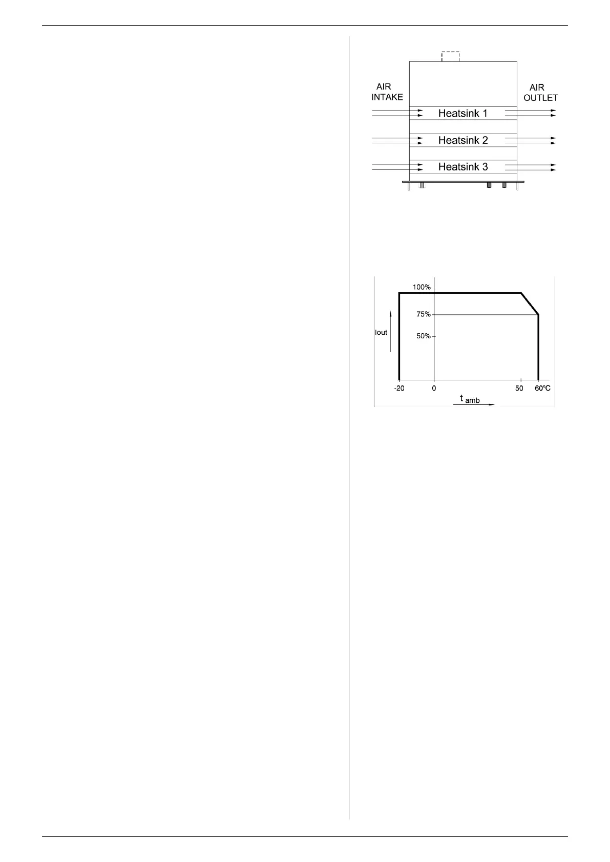
Three low noise blowers cool the unit. The speed of the fans
depends on the temperature of the internal heatsinks (see
fig. 4 - 9). Normally, at 50 °C ambient and full load the fans
will not work at full speed.
Due to the air that enters on the left and exits on the right, it is
possible to stack the power supplies. No distance between
the units is required.
4.26
At full power, the operating temperature range is –20 to
+50 °C. From 50 to 60 °C the output current (either positive or
negative) has to be derated linearly to 75% at 60 °C (see fig.
4 - 10). These temperatures hold for normal operation, i.e. the
air intakes & air outlets on the left and right side must be free.
4.27
A thermal protection circuit shuts down the output in case of
insufficient cooling. The display will show a thermometer
symbol and the OT-status will be active. After cooling down,
the unit will start working again.
4.28
Regularly check for firmware updates at the Delta Elektronika
website. If there is a new update available, the unit can be
updated via the web interface.
This document is based on firmware version P0140.
fig 4 - 9
The fans blow through the tunnels where
the heatsinks are situated.
fig 4 - 10
Operating temperature ranges.
Note the current derating is the same for
either sink or source mode.

 Loading...


