INSTALLATION SM15K
13 / 32 DELTA ELEKTRONIKA B.V. rev. January 2021
The unit can operate only on a 3 phase grid (see fig. 5 - 2),
see the chapter 'Specifications' for the minimum and
maximum values.
No neutral connection is required.
After installation, connect the pull relief and add the safety
cover over the AC terminals.
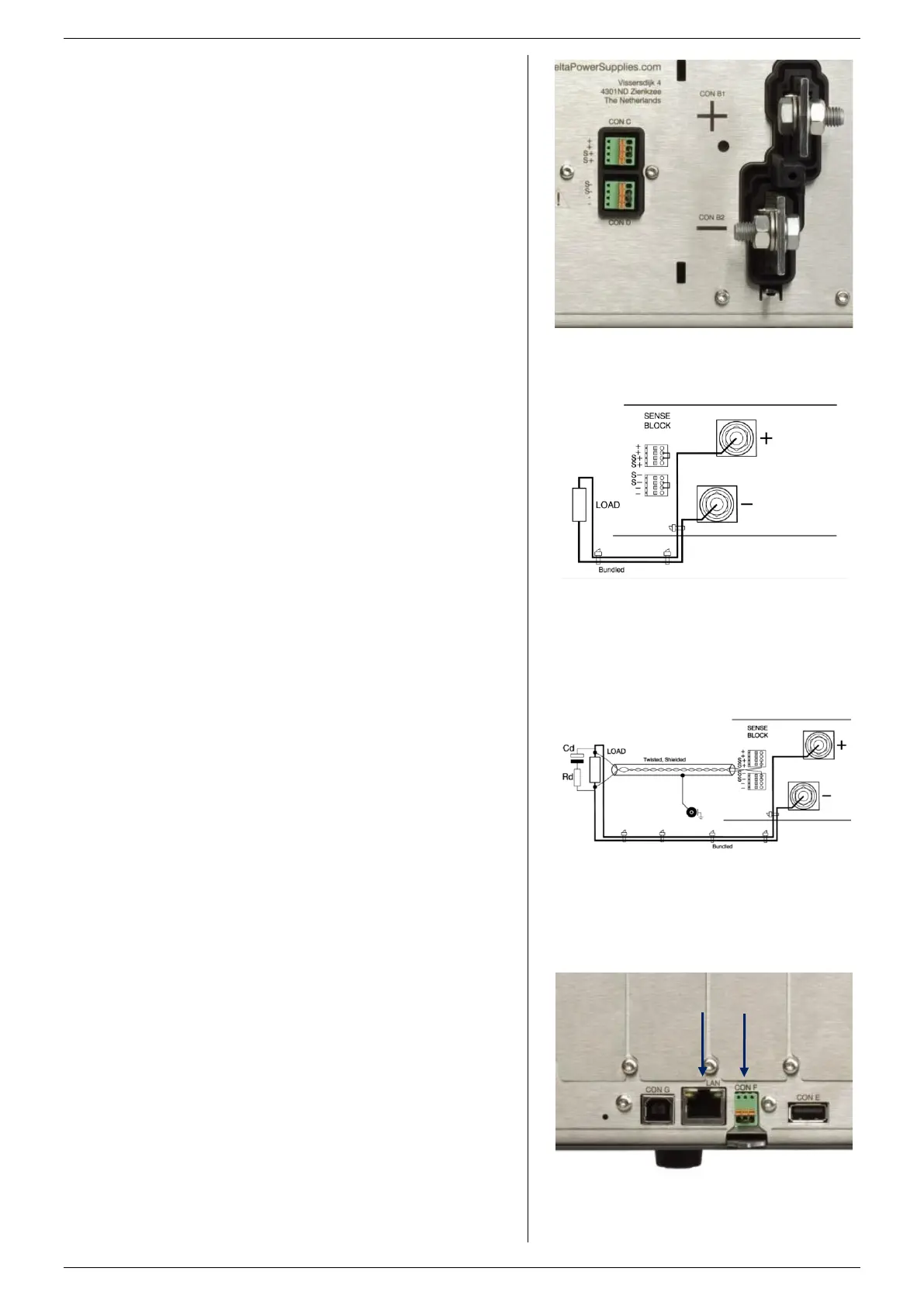
These terminals are located at the rear side, marked as CON
B1 (PLUS) and CON B2 (MINUS) (see fig. 5 - 3).
For cable diameters and mounting torque see table 5 - 1.
Use cables with a sufficient voltage rating for the output
voltage of the unit.
With high output current, make sure to use low resistive
connections between the power supply and the load:
- Mount the cable lugs directly on the DC power strips
followed by a washer, a split washer and a nut.
Always in this order!
- Never place washers between the lugs and the strips
because this can result in excessive heat!
- Only use nuts and washers supplied with the unit.
Minimize the inductance in the leads by keeping them close to
each other or by using a multi-strand cable.
The DC power terminals are floating in relation to Protective
Earth.
After installation mount the safety cover over the DC power
terminals.
5.4.3 DC LOAD SENSING (REMOTE SENSING)
These connectors are located at the rear side, marked as
CON C and CON D (see fig. 5 - 3).
Use the included 4-pole headers for connecting the sense
wires to the unit. By pressing the orange clips with a small
screwdriver, the wires can be inserted or released.
For local sensing, check whether there is a link between +
and S+ and between – and S– on the sense header (default),
see fig. 5 - 4.
For remote sensing, please first read paragraph 6 of this
chapter for more details.
To use remote sensing, remove the links between + and S+
and – and S– and connect sense leads to the inputs for S+
and S–.
The connectors enable the use of 2 sets of sense wires but
one set is sufficient.
Use cables with a diameter of 0.3 ... 0.5mm
2
and with a
sufficient voltage rating for the DC output voltage of the unit.
The leads are only thin measuring wires but always have to
be shielded. In order to prevent interference, it is advisable to
twist the leads. See fig. 5 - 5.
With regards to safety, the sense terminals are at the level of
the DC power terminals.
After installation mount the safety cover over the sense
terminals.
This connector is located at the rear side, marked as LAN
(see fig. 5 - 6).
For Ethernet programming or Web Interface control, insert a
standard RJ45 cable in the LAN connector at the rear side.
With regards to safety, the LAN connector is at the level of
Protective Earth.
5.4.5 INTERLOCK CONNECTOR
This connector is located at the rear side, marked as CON F
(see fig. 5 - 6).
Use the included 3-pole header for connecting the interlock
wires to the unit. By pressing the orange clips with a small
screwdriver, the wires can be inserted or released.
For more details and specifications about Interlock, please
read paragraph 7 'Interlock Function' in this chapter.
When the Interlock function is not used, connect a link
between terminal 1 and 3 of the Interlock header (default).
fig 5 - 3
The two DC power terminals CON B1 and B2.
Con C and D are the sensing connectors.
fig 5 - 4
Local sensing with the power cables bundled close
together to minimize inductance.
fig 5 - 5
Remote sensing with shielded twisted wires and
the power cables bundled close together to
minimize inductance.
fig 5 - 6
The location of the LAN-connector (left) and the
Interlock connector (right) at the rear panel.

 Loading...


