REMOTE PROGRAMMING SM15K
27 / 32 DELTA ELEKTRONIKA B.V. rev. January 2021
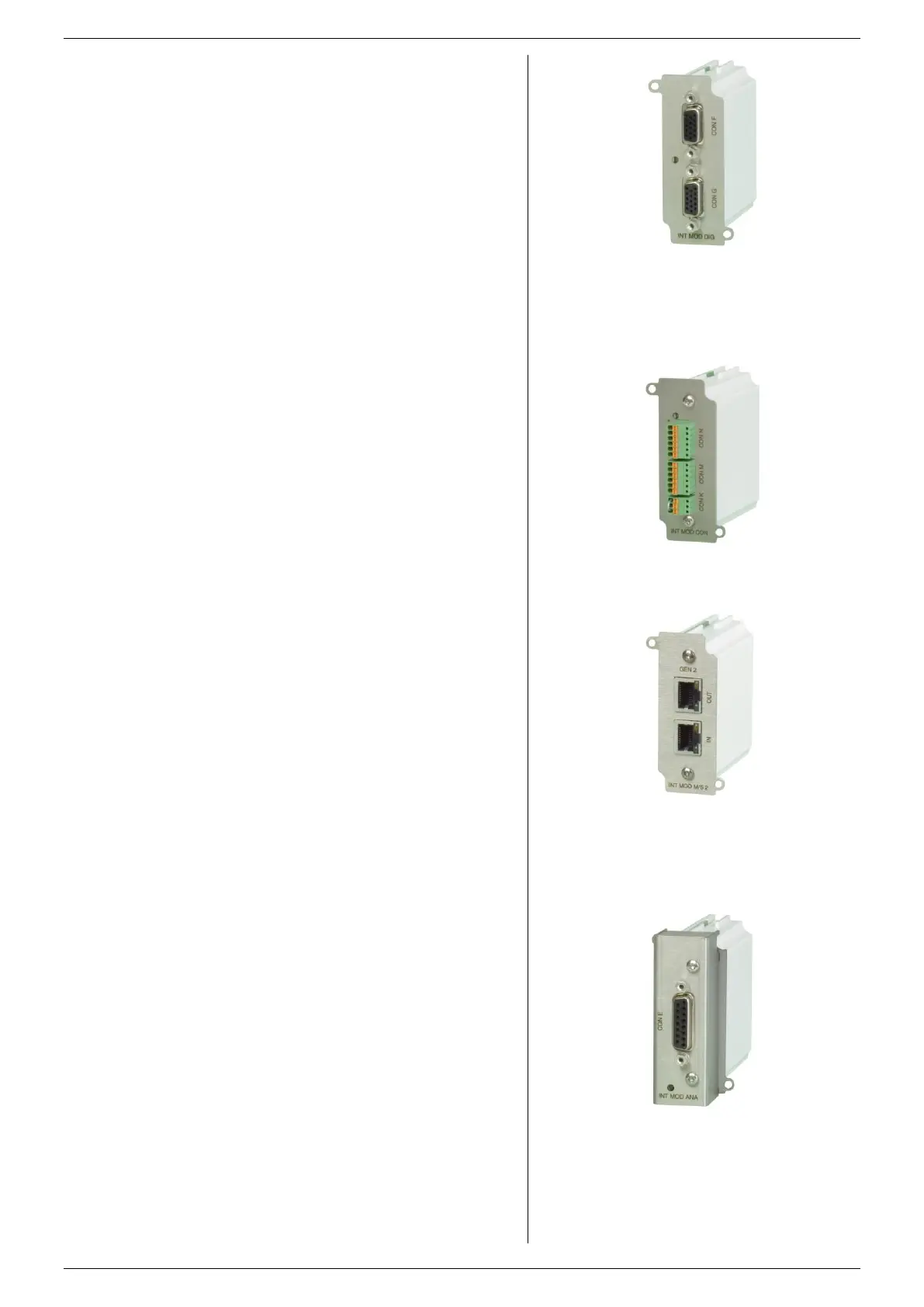
fig 7 - 9
Isolated Contacts
Set the programming source for voltage and/or current to
'slot1...4' via the front menu, the web interface or Eth
commands.
The following interfaces can be plugged in the slots at the
rear panel of the unit. There is room to insert a total of 4
interfaces (see fig. 7 - 7 ... 11).
7.5.1 SERIAL & USB PROGRAMMING
The protocols RS232, RS422, RS485 and USB (Virtual COM)
are supported by this interface.
With this interface it is possible to program the CV- and CC-
settings, to read the CV- and CC-monitor values and the
internal status signals.
See datasheet and manual of the INT MOD SER for more
information.
Maximum 4pcs of this type of interface per unit.
This interface provides 8 opto-isolated logic inputs and 8
opto-isolated logic open drain outputs.
All in- and outputs have a common zero.
Also see datasheet and manual of the INT MOD DIG.
Maximum 4pcs of this type of interface per unit.
On this interface, there are 4 floating relay contacts available
that can be controlled by Ethernet commands.
This can be used to trigger an external safety alarm or to
interact in automated processes.
Floating Interlock connector (standard Interlock is at the level
of Safety Earth).
Floating Enable input to switch the output On/Off (24Vdc).
See datasheet and manual of the INT MOD CON for more
information.
Note: the floating relay contacts can not be controlled by the
sequencer.
Maximum 4pcs of this type of interface per unit.
7.5.4 MASTER / SLAVE CONTROL
The resulting combination behaves like one power supply and
can be manually controlled or programmed on the master.
Mixed parallel - series operation is not possible.
Note1: max 1pcs M/S-2 interface possible per unit.
Note2: the M/S-2 interface is for SM15K-units only, the M/S
interface is for SM3K3 units only.
Also see datasheet and manual of the IND MOD M/S-2.
7.5.5 ISOLATED ANALOG PROGRAMMING
With this interface it is possible to program the CV- and CC-
settings using a 0 - 5V or 0 - 10V voltage source.
The CV- and CC-monitor signals can be measured with a volt
meter (0 - 5V or 0 - 10V). Also available are the 5V logic
status signals, Remote ShutDown (RSD = 5V), an auxiliary
voltage (+12V) and a reference of 5.1V.
Because the interface is isolated from the power output, earth
loops between the programming source and the power supply
are prevented.
All connections are pin compatible with other Delta
Elektronika power supplies such as ES150, SM3300, SM800,
SM1500, SM6000 etc.
Note: maximum 1 analog interface possible per unit.
Also see datasheet and manual of the INT MOD ANA.
fig 7- 8
Digital I/O Module.
fig 7 - 10
Master Slave interface M/S-2.
Note: the M/S-2 can only be used in SM15K
fig 7 - 11
Isolated Analog interface
 Loading...


