REMOTE PROGRAMMING SM15K
26 / 32 DELTA ELEKTRONIKA B.V. rev. January 2021
Select which type of Function Block to use:
- Internal Resistance
- Leadless Sensing
- Photovoltaic Simulation
Make the settings for the parameters and select its
programming sources.
Configure the power supply program sources to use the
function block as program source for its output controllers.
See Function Blocks Manual for more information and
examples on our website.
Here a new firmware package can be uploaded.
INFO
System information
- Unit.
- Serial number.
- Manufacturer.
- Software version.
- Internal error.
Highlight button
- Display on front will blink for about 2 seconds.
- Buzzer on front is on for about 2 seconds.
LOGGING
Ethernet communication
- Download log file.
- Log settings displayed.
PASSWORD
Change the password to block the unit.
The default password is "depower".
Passwords are not case sensitive.
In case of a forgotten password see next chapter Trouble
Shooting.
Unit documentation in PDF-format available:
- Safety instructions.
- Unit operation and installation manual.
- Interfaces operation and installation manual.
- Ethernet & Sequencer programming manual.
7.3
The ETH interface is available 15s after start up of the unit.
Connect the unit to the network via the LAN-connector at the
rear side, see fig 7 - 4.
Download the programming manual for Ethernet & Sequencer
via the web interface or via .
Set the programming source for voltage, current and/or power
to 'eth' via the front menu or the web interface.
7.4
Download the programming manual for Ethernet & Sequencer
via the web interface or via .
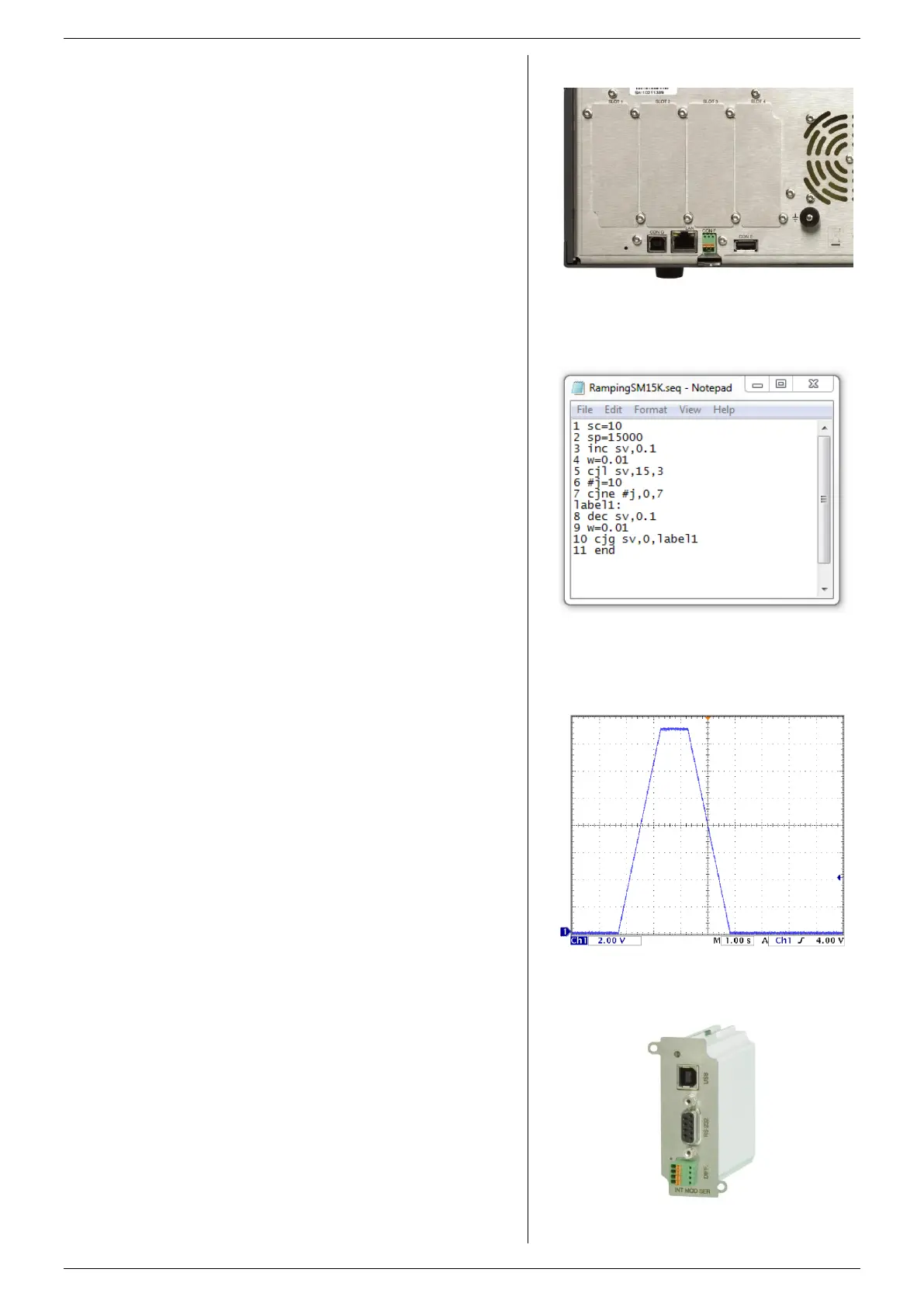
Define a sequence using a basic text editor, for example
Notepad. Save as "filename.seq". An example is shown in
fig. 7 - 5 and fig. 7 - 6.
Upload the sequence to the unit via the web interface or via
Eth programming commands.
Set the programming source for voltage, current and/or power
to 'seq' via the front menu, the web interface or Eth
commands.
Start/Stop the sequence via the web interface, Eth commands
or a hardware trigger via the Digital I/O interface.
Note: copy the uploaded sequences into the non-volatile
memory before switching off the unit. Standard they are
uploaded in the volatile memory and are lost after switching
off the mains.
fig 7 - 4
The location of the LAN-connector and the available
interface slots at the rear panel.
fig 7 - 6
Output voltage as result of the above example..
fig 7 - 7
Serial & USB Programming Module.
fig 7 - 5
Example of a small sequence to ramp up the output to
15V and then back to 0V.
 Loading...


