GENERAL SM15K
10 / 32 DELTA ELEKTRONIKA B.V. rev. January 2021
diode take care the output is switched to “ON” and the
negative current setting is sufficient to hold the current.
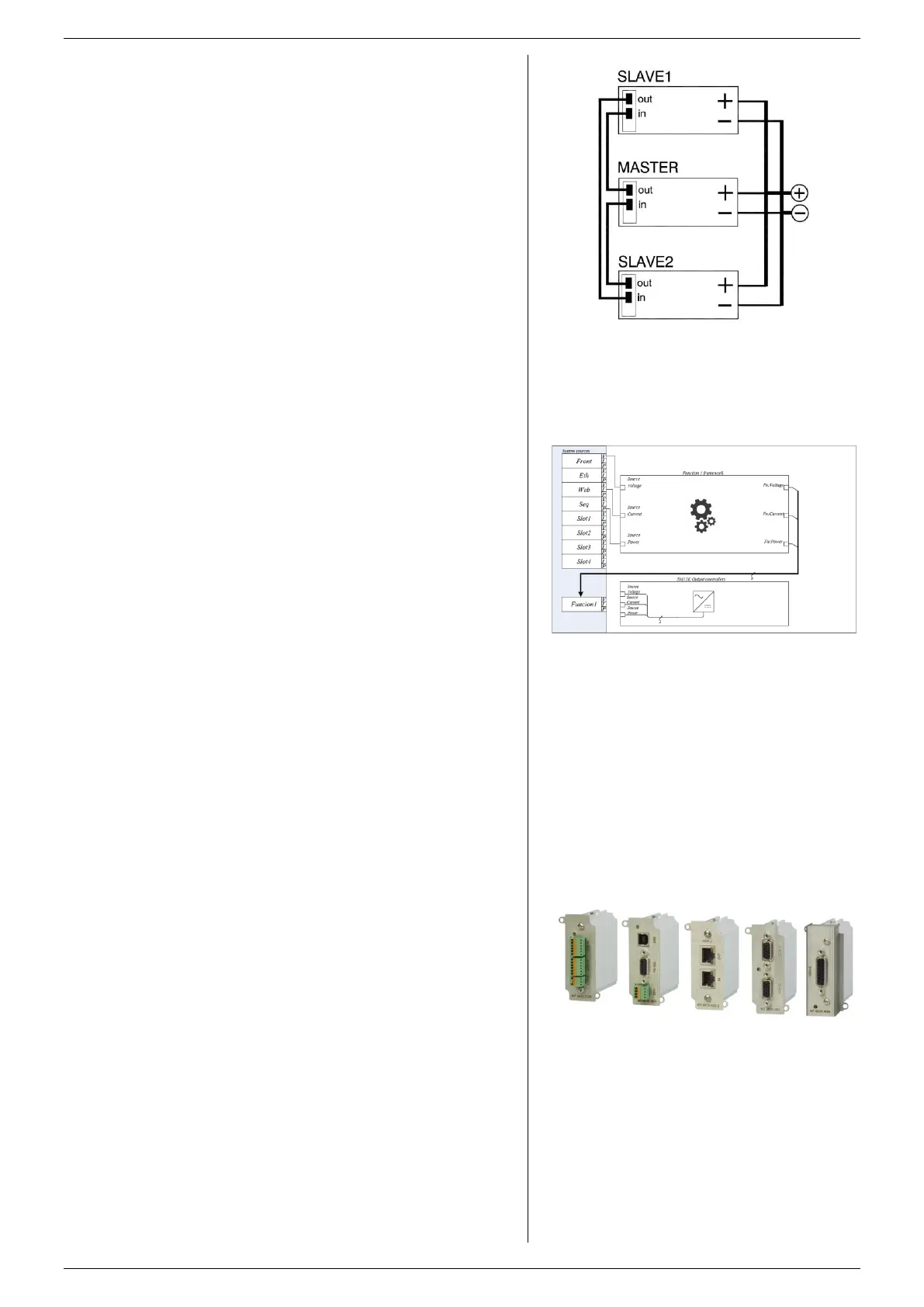
For easier control, the optional Master/Slave interface is
recommended (see fig.4 - 5).
4.18
Without Master/Slave interface, only one unit can operate in
the Bi-Directional mode, all others can only be used as power
source.
With the optional Master/Slave interface (see fig. 4 - 6) the
power supplies can be connected in parallel without
limitations and with full functionality.
4.19
The Interlock connector at the rear panel has two pins which
have to be connected together to turn on the DC power
terminals of the unit.
As soon as the link between the 2 outer pins of the Interlock
connector is interrupted, the DC power output of the unit
shuts down.
It can be used in combination with a cabinet door contact
(safety precaution) or as an emergency brake to stop a motor
which is powered by the unit. Once the interlock pins are
connected again, the DC power output will be on.
4.20
WEB INTERFACE, ETH & USB PROGRAMMING
The web interface and Ethernet are standard available on all
units via the LAN connector at the rear side.
Also a USB connector is standard available but USB
programming is still under development for firmware version
P0140.
The web interface can be used to view and change the
settings for CV, CC+, CC-, POWER+, POWER-, Output
On/Off, configure the sink mode or optional interfaces, to
upload new firmware and configure the unit similar as with the
front display menu.
With the build-in Ethernet interface it is possible to program
the CV/CC/CP-settings, to read the CV/CC-monitors and the
status signals.
4.21
Possibility to use the unit in stand-alone automation or use as
an arbitrary waveform generator and create loops, ramps etc.
The sequencer can be controlled via the web interface and
via Ethernet programming.
4.22
With the new SM15K series Delta introduces “Integrated
Function Blocks’.
Integrated Function Blocks are functional integrated software
blocks with predefined behavior that can be put in between a
program source and the units output controllers, see fig. 4 - 7.
By using these Integrated Function Blocks the user is able to
manipulate the units Program sources or can setup specific
simulations.
See "Function Blocks Manual" for more information and
examples.
The Integrated Function Block “Leadless sensing” is a
functional integrated software block with predefined behavior
that can be put in between a program source and the units
output controllers.
By using this Integrated Function Block the user is able to
compensate a voltage drop falling over long or high resistive
load cables.
4.22.2 INTERNAL RESISTANCE
The Integrated Function Block “Internal Resistance” is a
functional integrated software block with predefined behavior
that can be put in between a program source and the units
output controllers.
fig 4 - 8
Different interface modules can be plugged in.
fig 4 - 6
Optional Master/slave parallel operation.
fig 4 - 7
Functions Blocks can be put in between a program
source and the units output controllers.

 Loading...


